

OELD (Organic Electroluminescent Device) and preparation method thereof
An electroluminescent device, an organic technology, applied in the direction of electric solid-state devices, semiconductor/solid-state device manufacturing, electrical components, etc., can solve the problems of high price and low device efficiency
- Summary
- Abstract
- Description
- Claims
- Application Information
AI Technical Summary
Problems solved by technology
Method used
Image


Examples
Embodiment 1
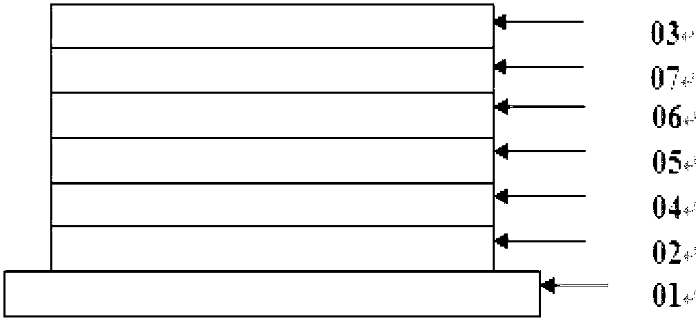
[0058] In this example, yellow light-emitting devices with different doping concentrations of fluorescent dyes were prepared, and these devices have such as image 3 structure shown. The light-emitting layer contains a host material (Host 1) and a fluorescent dopant dye (YD 1), wherein the energy level difference between the triplet state and the singlet state of the Host 1 material is 0.1eV, and the singlet state energy level of YD1 is 2.2eV, which is lower than The singlet energy level of Host 1. The structural formulas of Host1 and YD 1 are as follows:
[0059]
[0060] The device structure of this embodiment is as follows:
[0061] ITO (150nm) / NPB (40nm) / Host 1: (0.01%, 0.5%, 1.0%, 5%) YD 1 (30nm) / Alq 3 (20nm) / LiF(0.5nm) / Al(150nm)
[0062] Wherein, the percentages in parentheses before YD1 indicate different doping concentrations of fluorescent dyes, and in this embodiment and the following, the doping concentrations are all weight %.
[0063] The specific preparat...
Embodiment 2
[0081] In this example, yellow light-emitting devices with different doping concentrations of fluorescent dyes were prepared, and these devices have such as image 3 structure shown. The light-emitting layer contains a host material (Host 2) and a fluorescent doped dye (YD 1), where the energy level difference between the triplet state and the singlet state of the Host2 material is 0.1eV, and the singlet state energy level of YD1 is lower than that of Host 2. state energy level. The structural formula of Host 2 is as follows:
[0082]
[0083] The device structure of this embodiment is as follows:
[0084] ITO (150nm) / NPB (40nm) / Host 2: (0.01%, 0.5%, 1.0%, 5%, 10%) YD 1 (30nm) / Alq3 (20nm) / LiF (0.5nm) / Al (150nm)
[0085] Wherein, the percentages in parentheses before YD1 indicate different doping concentrations of fluorescent dyes, and in this embodiment and the following, the doping concentrations are all weight %.
[0086] The specific preparation method of the organic...
Embodiment 3
[0097] In this example, red light-emitting devices with different doping concentrations of fluorescent dyes were prepared, and these devices had such image 3 structure shown. The light-emitting layer contains a host material (Host3) and a fluorescent dopant dye (RD 1). The energy level difference between the triplet state and the singlet state of Host3 is 0.11eV, the energy level of the singlet state of RD1 is 2.0eV, and the energy level of the singlet state of RD1 is lower than that of Host 3. The structural formulas of Host3 and RD1 are as follows:
[0098]
[0099] Prepare an organic electroluminescence device in the same manner as in Example 1 above, and the structure of the light-emitting device is as follows:
[0100] ITO (150nm) / NPB (40nm) / Host 3: (0.01%, 0.5%, 1.0%, 5%, 10%) RD 1 (30nm) / Bphen (20nm) / LiF (0.5nm) / Al (150nm)
[0101] Among them, the percentages in parentheses before RD1 indicate different fluorescent dye doping concentrations.
PUM
 Abstract
Description
Claims
Application Information