Electrolyte filling device of lithium ion batteries

A technology of lithium ion battery and liquid injection device, which is applied in battery pack parts, circuits, electrical components, etc., can solve the problems of increased equipment investment, decreased production efficiency, and increased production cost of battery cells.

Active Publication Date: 2012-10-03
NINGDE AMPEREX TECH
View PDF4 Cites 19 Cited by
  • Summary
  • Abstract
  • Description
  • Claims
  • Application Information

AI Technical Summary

Problems solved by technology

Therefore, in the current process, after liquid injection, it is often necessary to increase the standing time and increase the standing temperature to ensure the full infiltration of the diaphragm, which brings about a decrease in production efficiency, an increase in equipment investment, and ultimately leads to the production cost of the battery cell. increase

Method used


Image

  • Electrolyte filling device of lithium ion batteries
  • Electrolyte filling device of lithium ion batteries
  • Electrolyte filling device of lithium ion batteries

Examples


Embodiment 1

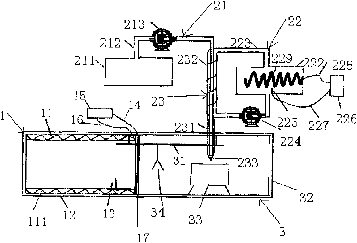
[0027] Such as figure 1 As shown, a lithium-ion battery liquid injection device includes a liquid injection system 3, a cell preheating system 1 and / or an electrolyte heating system 2, and the cell preheating system 1 is the upper station of the liquid injection system 3 And a cell outlet 17 is provided between the two, and the electrolyte heating system 2 is located above the liquid injection system 3 .

[0028] The battery preheating system 1 includes a battery heat supply system 11, a battery heat preservation chamber 12 and a temperature control circuit 15 for controlling the temperature in the battery heat preservation chamber 12, and the battery heat supply system 11 is located at The resistance wire 111 inside the cell insulation cavity 12 .

[0029] The temperature control circuit 15 includes a first temperature-sensing probe 13 arranged inside the cell insulation cavity 12, a first temperature-regulating controller 15, and a first temperature-sensing probe 13 for con...

Embodiment 2

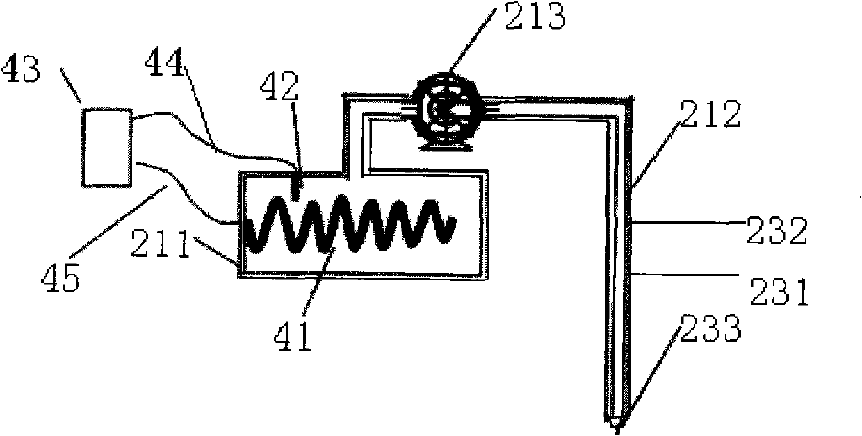
[0038] The structure of the electrolyte heating system 2 of this embodiment is different from that of Embodiment 1. This embodiment uses a resistance wire direct heating system, and the rest is the same as that of Embodiment 1, and will not be repeated here.

[0039] refer to figure 2 , the resistance wire heating system includes a resistance wire 41 arranged in the electrolyte storage tank 211, a third temperature-sensing probe 42 arranged in the electrolyte storage tank 211, a third temperature probe 42 arranged outside the electrolyte storage tank 211 A temperature adjustment controller 43, a third temperature sensing line 44 for connecting the third temperature sensing probe 42 and the third temperature adjustment controller 43, the third temperature adjustment controller 43 passes through the third resistance wire wire 45 is connected with the electrolyte storage tank 211.

[0040] When working, turn on the power supply, the resistance wire 41 starts to work, and the el...

Embodiment 3

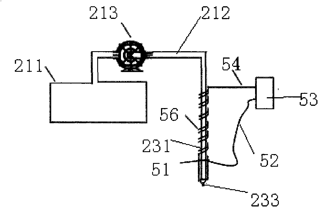
[0043] The structure of the electrolyte heating system 2 is different from that of the embodiment 1, and the cells are not heated. This embodiment uses an infrared heating system, and the rest is the same as that of the embodiment 1, which will not be repeated here.

[0044] refer to image 3 , the infrared heating system includes an infrared heating tube 56 sleeved outside the heat exchanger 231, a fourth temperature-sensing probe 51 arranged outside the catheter tube 212, and the fourth temperature-sensing probe 51 through a fourth temperature-sensing The fourth temperature adjustment controller 53 connected with the line 52 , the fourth temperature adjustment controller 53 is connected with the infrared heating tube 56 through the fourth resistance wire 54 .

[0045] When working, turn on the power, the infrared heating tube 56 starts to work, heats the electrolyte, the fourth temperature sensing probe 51 senses the temperature of the electrolyte, and transmits the signal t...


PUM


Abstract

The invention relates to the technical field of lithium ion batteries, in particular to an electrolyte filling device for lithium ion battery electrolyte rapidly infiltrating membranes. The electrolyte filling device comprises an electrolyte filling system, a battery core pre-heating system and / or an electrolyte heating system, wherein the battery core pre-heating system is an upper station of the electrolyte filling system and a battery core outlet is arranged in between the battery core pre-heating system and the electrolyte filling system, and the electrolyte heating system is arranged on the electrolyte filling system. During electrolyte filling process, the battery core and / or the electrolyte is heated to a certain temperature, so that viscosity of the electrolyte is the infiltration process is reduced, and rapid infiltration is achieved. Accordingly, the electrolyte filling device can effectively relieve the problem of slow electrolyte infiltration after electrolyte filling, so that standing time between electrolyte infiltration and formation is reduced, and the production efficiency is improved.

Description

technical field [0001] The invention relates to the technical field of lithium-ion batteries, in particular to a liquid injection device for rapidly infiltrating a diaphragm with an electrolyte of a lithium-ion battery. Background technique [0002] With the development of modern society, more and more mobile electronic devices are born, and the demand for lithium-ion batteries is increasing year by year; but correspondingly, a large number of lithium-ion battery manufacturers have sprung up. Since then, there has been fierce market competition among battery manufacturers. In order to ensure that the produced batteries have sufficient price advantages, it is necessary to control the production cost of batteries and improve the production efficiency of batteries. [0003] In the existing production process of flexible packaging cells, most of them use normal pressure liquid injection. In this case, the micropores of the diaphragm are filled with air before liquid injection, ...

Claims


Application Information

Patent Timeline
Patent Type & Authority Applications(China)
IPC IPC(8): H01M2/36
CPCY02E60/12Y02E60/10
Inventor 游从辉李白清徐延杰杨玉洁江辉方宏新张柏清
Owner NINGDE AMPEREX TECH
Why Eureka
Try Eureka