
Impact current eliminating circuit

A technology for inrush current and circuit elimination, applied in the direction of electric lamp circuit layout, electric light source, electrical components, etc., can solve the problems of reduced circuit output efficiency and increased conduction voltage drop, and achieves slow conduction speed and conduction voltage drop. The effect of reducing and improving the overall output efficiency

Active Publication Date: 2014-06-25
SILERGY SEMICON TECH (HANGZHOU) CO LTD
View PDF7 Cites 0 Cited by
  • Summary
  • Abstract
  • Description
  • Claims
  • Application Information

AI Technical Summary

Problems solved by technology

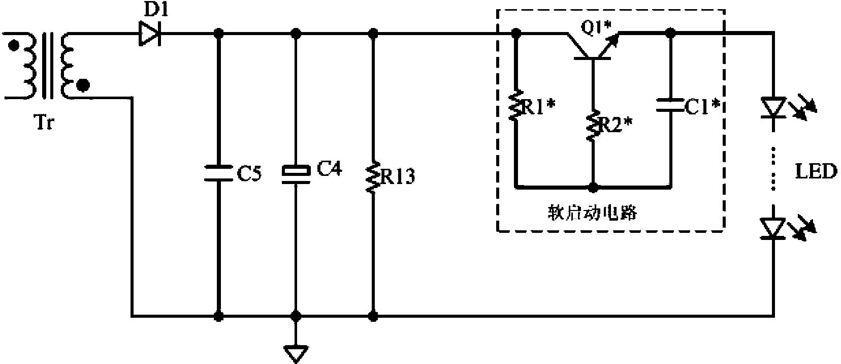
[0006] In the formula (1), β is the amplification factor of the switching tube Q1*, I LED is the drive current of the LED load, it can be seen from the formula (1), the conduction voltage drop of the switch tube Q1* is at least 0.7V, and it is related to the drive current of the LED load, when the drive current of the LED When it is larger, its conduction voltage drop will further increase. Such a large conduction voltage drop value will cause a large power loss in the circuit, so that the overall output efficiency of the circuit will be reduced.

Method used


Image

  • Impact current eliminating circuit
  • Impact current eliminating circuit
  • Impact current eliminating circuit

Examples


Embodiment Construction

[0031] Several preferred embodiments of the present invention will be described in detail below with reference to the accompanying drawings, but the present invention is not limited to these embodiments. The present invention covers any alternatives, modifications, equivalent methods and schemes made on the spirit and scope of the present invention. In order to provide the public with a thorough understanding of the present invention, specific details are set forth in the following preferred embodiments of the present invention, but those skilled in the art can fully understand the present invention without the description of these details.

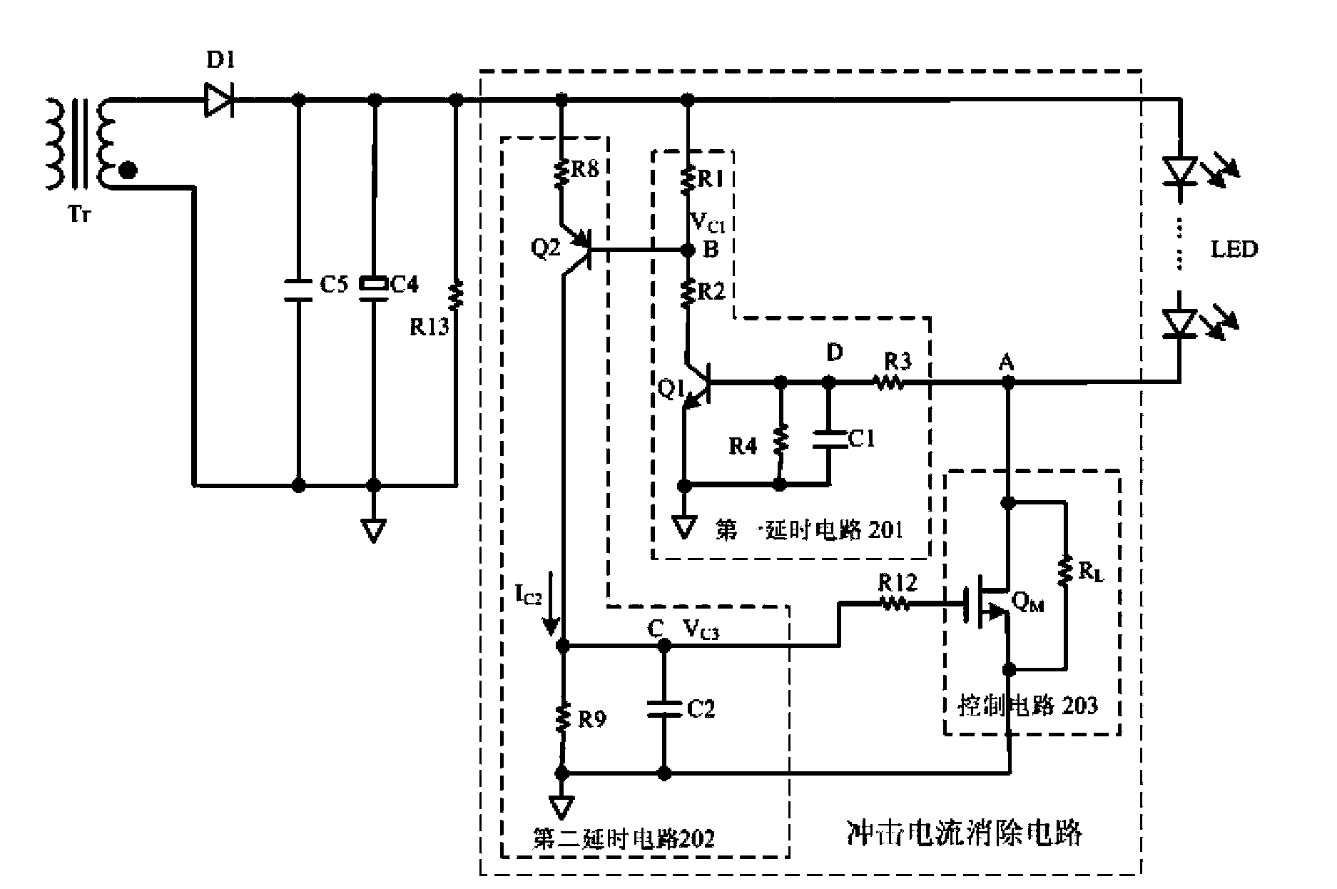
[0032] refer to figure 2 , shows the circuit diagram of the first embodiment of an inrush current elimination circuit according to the present invention, the inrush current elimination circuit is applied in a switching power supply, such as figure 2 As shown, the switching power supply is used to supply a DC voltage to the LED load, an...


PUM


Abstract

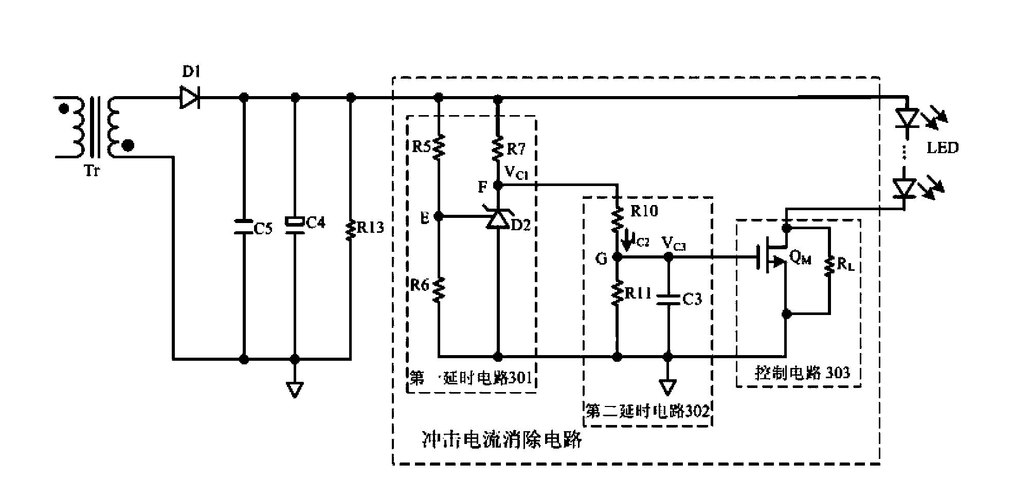
The invention discloses an impact current eliminating circuit which is applied to a switching power supply; two stages of delay circuits are used for controlling the soft start of a power switch tube so as to suppress the impact current during a starting process, so that the current of a light-emitting diode (LED) is maintained at a minimum value, and the impact of the impact current on the load of the LED is eliminated; in addition, the minimum communication voltage drop of the circuit is greatly reduced compared with that in the prior art; and consequently, the power loss is smaller, and the overall output power of the circuit is improved.

Description

technical field [0001] The invention relates to the technical field of power electronics, and more specifically, relates to an inrush current elimination circuit applied to a switching power supply. Background technique [0002] In the process of using the switching power supply to supply power to the LED load, when the LED load is powered on, a large inrush current will often be generated. The amplitude of the inrush current is greater than the maximum current value that the LED load can withstand. Therefore, it is necessary to This inrush current is limited or eliminated to prevent the LED load and other circuit components from being damaged. [0003] refer to figure 1 , shows the circuit diagram of an existing soft-start inrush current elimination circuit. When the secondary side voltage of the converter Tr in the switching power supply is rectified and filtered, a voltage is output. The voltage is first passed through the resistor R1* to the capacitor C1*. Charging, wh...

Claims


Application Information

Patent Timeline
Patent Type & Authority Patents(China)
IPC IPC(8): H05B37/00H02M1/32
Inventor 徐鸿国韩云龙
Owner SILERGY SEMICON TECH (HANGZHOU) CO LTD
Learn More