Water-saving system and water-saving process thereof used in wet desulfurization process
A technology of wet desulfurization and water-saving system, which is applied in separation methods, chemical instruments and methods, and separation of dispersed particles, etc., to achieve recycling, significant environmental protection effects, and simple settings
- Summary
- Abstract
- Description
- Claims
- Application Information
AI Technical Summary
Problems solved by technology
Method used
Image
Examples
Embodiment 1
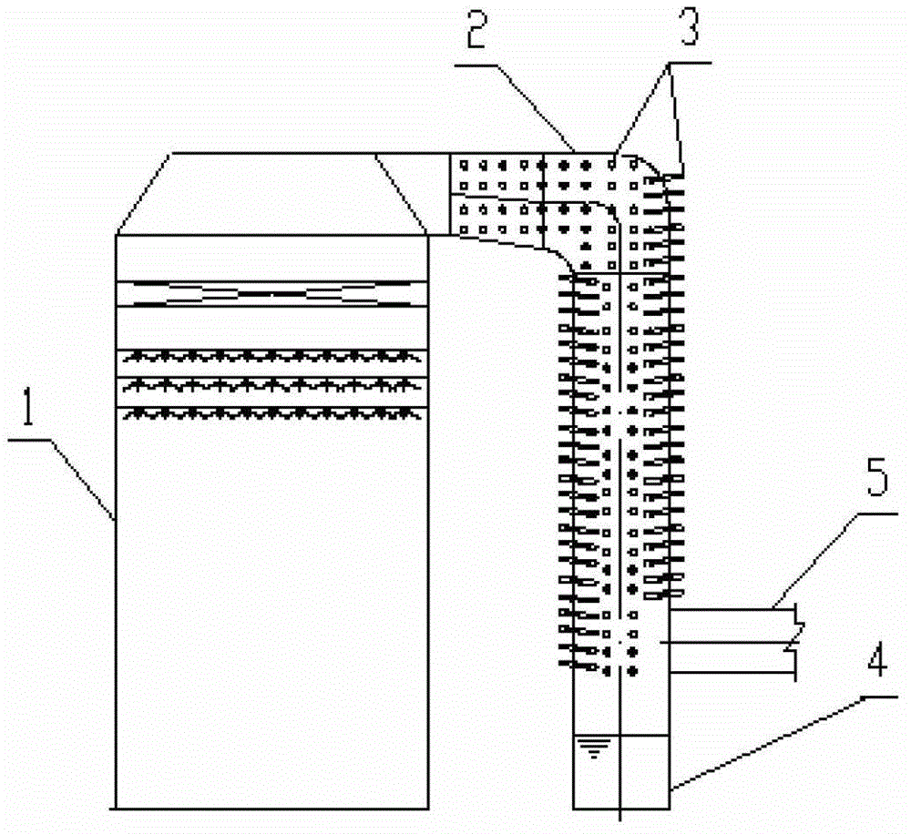
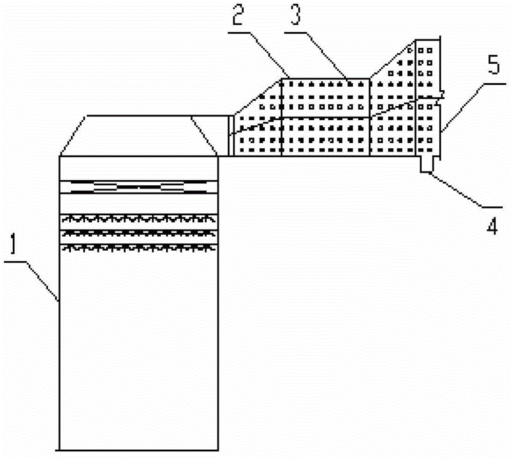
[0031] Such as figure 1 As shown, the water-saving system for the wet desulfurization process includes an absorption tower 1, a chimney 5, a clean flue 2, a plurality of heat pipes 3 arranged in sequence along the flue gas flow direction on the flue wall of the clean flue 1, and Storage device 4; wherein, the storage device 4 is arranged at the end of the clean flue 2; each heat pipe 3 is evenly distributed in the clean flue 2 and arranged obliquely, the downwardly inclined part is in the clean flue 2, and the upwardly inclined part is in the clean flue Clean flue 2 outside;
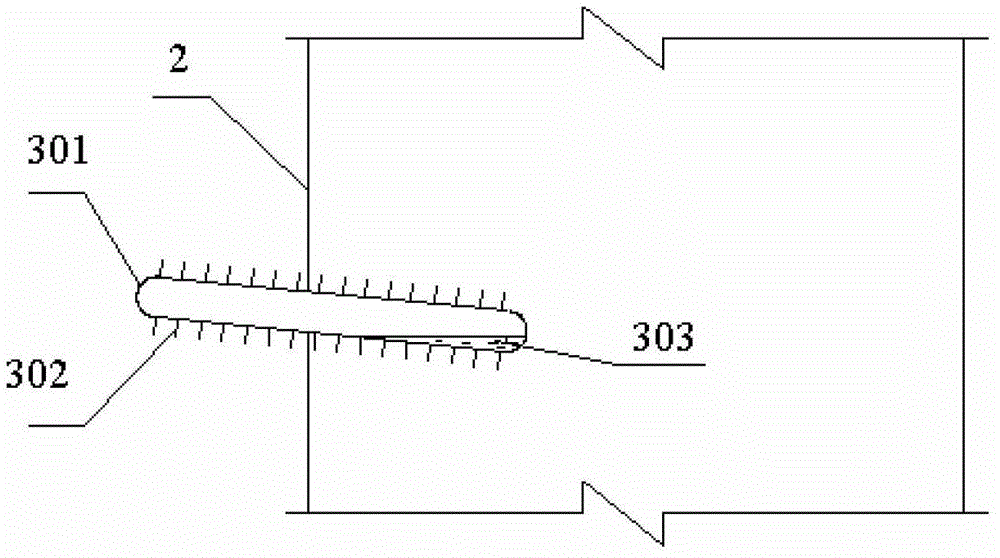
[0032] Such as figure 2 As shown, the heat pipe 3 includes a shell 301 and fins 302 arranged on the shell 301 , the fins 302 can increase the contact area accordingly, which is beneficial to improve the recovery efficiency.
[0033] In the above-described embodiment, each heat pipe 3 is not provided with fins 302 on the housing 301 in the clean flue 2, so as to prevent the dust and dirt inside the cle...
Embodiment 2
[0045] Such as figure 1 and figure 2 As shown, the setting and distribution of a water-saving system for wet desulfurization process are the same as in Example 1, except for the following settings: the specification of the clean flue 2 is 5m×6m, the diameter of the heat pipe 3 is 100mm, and the fins 302 The spacing of the heat pipes 3 is 2.5mm, the length of the heat pipes 3 in the clean flue 2 is 1.50m, and the distribution distance of the heat pipes 3 on the clean flue 2 is 400mm.
[0046] Applying the water-saving system of the present invention for wet desulfurization process to carry out the water-saving process of cleaning flue gas is the same as embodiment 1, except the following steps:
[0047] In step (1), the vacuum pressure inside the heat pipe 3 is 1×10 -4 Pa;
[0048] In step (2), the temperature of the net flue gas exiting the absorption tower 1 is 55°C, and the flue gas volume is 1.2×10 6 N m 3 / h, the ambient temperature is 5°C, the partial pressure of wa...
Embodiment 3
[0051] Such as figure 1 and figure 2 As shown, the setting and distribution of a water-saving system for wet desulfurization process are the same as in Example 1, except for the following settings: the specification of the clean flue 2 is 5m×6m, the diameter of the heat pipe 3 is 120mm, and the fins are 302 The spacing of the heat pipes 3 is 4mm, the length of the heat pipes 3 in the clean flue 2 is 2.5m, and the distribution distance of the heat pipes 3 on the clean flue 2 is 400mm.
[0052] Applying the water-saving system of the present invention for wet desulfurization process to carry out the water-saving process of cleaning flue gas is the same as embodiment 1, except the following steps:
[0053] In step (1), the vacuum pressure inside the heat pipe 3 is 10Pa;
[0054] In step (2), the temperature of the net flue gas exiting the absorption tower 1 is 60°C, and the flue gas volume is 1.5×10 6 N m 3 / h, the ambient temperature is 15°C, the partial pressure of water v...
PUM
 Abstract
Description
Claims
Application Information
 - R&D
- Intellectual Property
- Life Sciences
- Materials
- Tech Scout
- Unparalleled Data Quality
- Higher Quality Content
- 60% Fewer Hallucinations
Browse by: Latest US Patents, China's latest patents, Technical Efficacy Thesaurus, Application Domain, Technology Topic, Popular Technical Reports.
© 2025 PatSnap. All rights reserved.Legal|Privacy policy|Modern Slavery Act Transparency Statement|Sitemap|About US| Contact US: help@patsnap.com


