Automobile electronic safety device having dual energy and dual effect and being energy-saving and emission-reducing

A technology for energy saving, emission reduction, and electronic safety, which is applied in ignition safety devices, inductive energy storage devices, vehicle components, etc., and can solve problems such as insufficient voltage supply to ignition coils, waste of air, and weak electric sparks

Active Publication Date: 2012-10-10
谢自泉 +2
View PDF7 Cites 0 Cited by
  • Summary
  • Abstract
  • Description
  • Claims
  • Application Information

AI Technical Summary

Problems solved by technology

For example, when the power generation is insufficient, the power storage is insufficient, the battery is aging, malfunctioning, the circuit is aging, the vehicle electrical appliances are configured too much, the use is too frequent, etc., and the voltage is suddenly dropped, resulting in insufficient voltage for the ignition coil, so that the 12 Volts or 24 volts V low voltage is boosted to tens of thousands of volts to discharge and generate electric sparks to ignite combustible gases. If the low voltage power lacks 1 volt or 0.5 volts, the gap of high voltage pow

Method used


Image

  • Automobile electronic safety device having dual energy and dual effect and being energy-saving and emission-reducing
  • Automobile electronic safety device having dual energy and dual effect and being energy-saving and emission-reducing
  • Automobile electronic safety device having dual energy and dual effect and being energy-saving and emission-reducing

Examples


Embodiment Construction

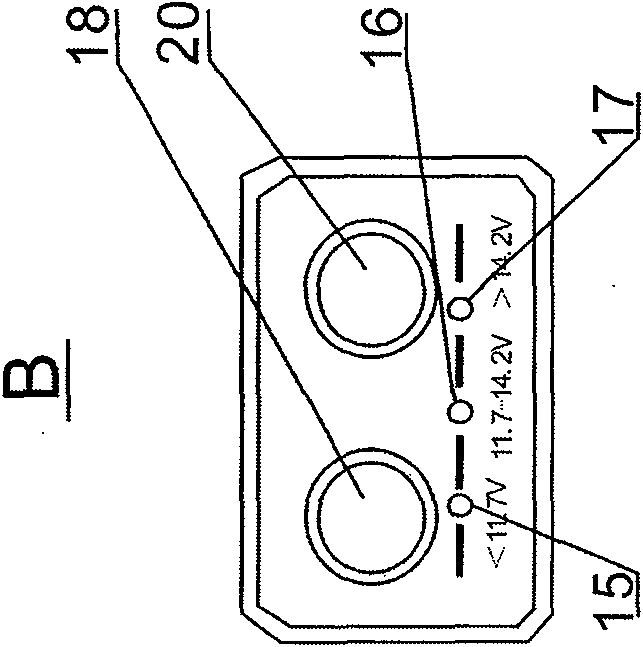
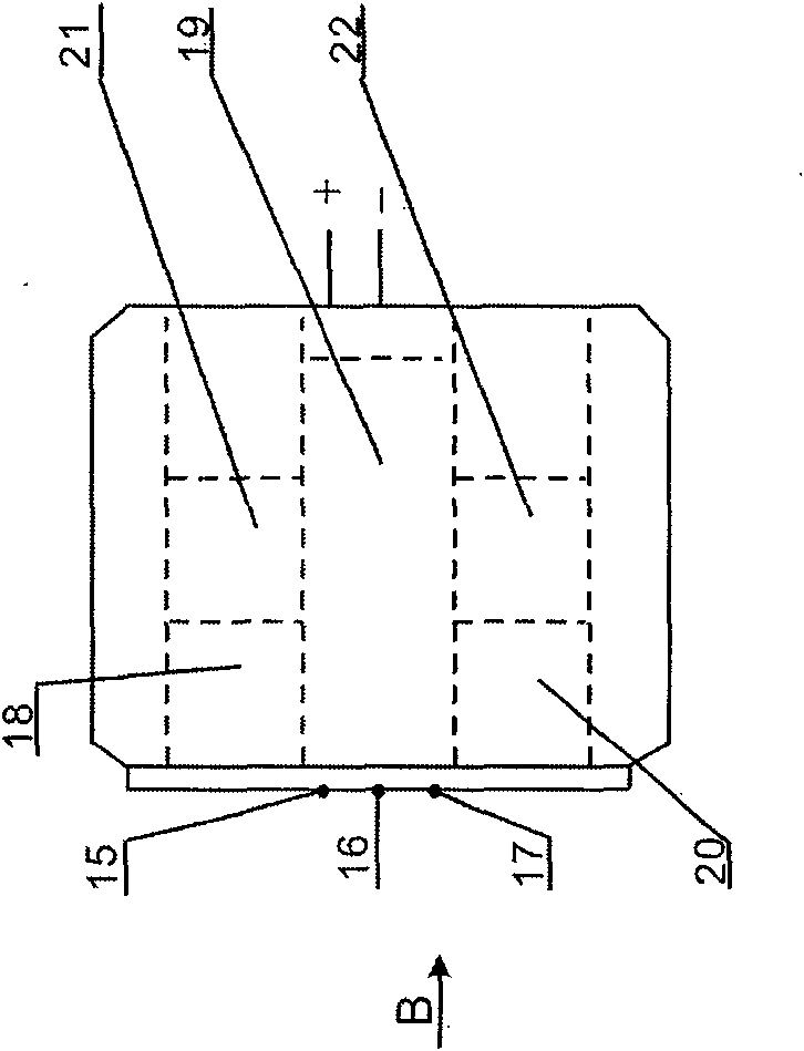
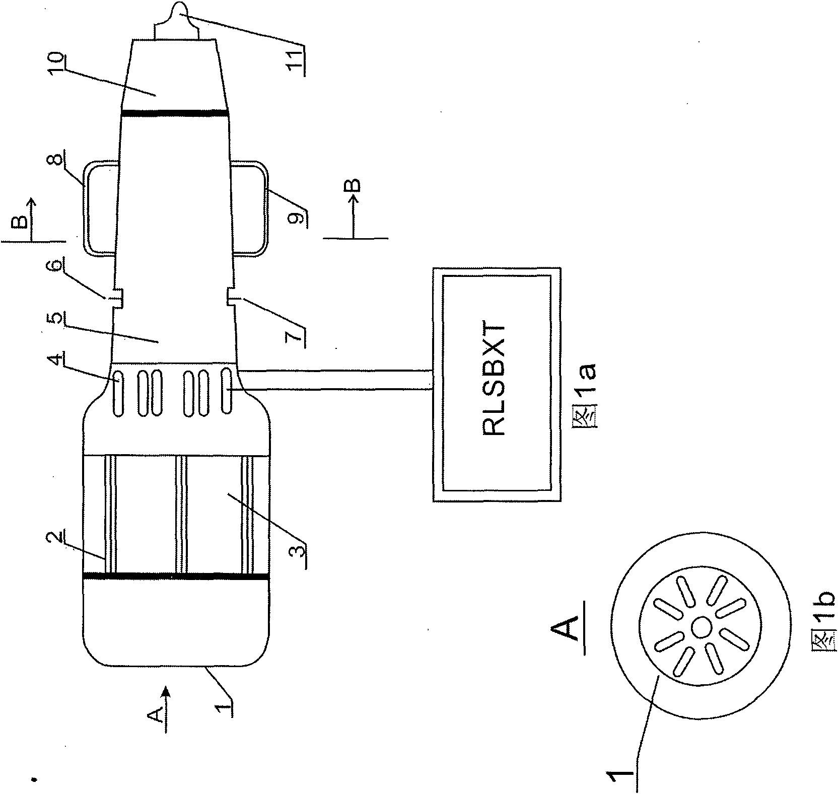
[0023] Such as Figure 1a and Figure 2a As shown, the host of the present invention consists of a front cover 1, two covers 5 up and down the body, and a terminal 10. Built-in circuit board and electronic components 12, compression spring 13, safety tube 14, cathode is made of electroplated spring steel 8,9. The anode metal cap 11 constitutes. Among them, the front cover 1, the upper and lower covers 5 of the body and the end 10 are molded black by ABS engineering plastics. Figure 1b Evenly establish pattern heat radiation decoration hole outside the middle part 4 of cover 5 up and down of the body. Simultaneously, the long sides of the upper and lower covers 5 of the body are respectively concave-convex grooves for fastening the upper and lower covers. There is a barb inside the front cover 1 and utilizes elasticity to press the upper and lower body 5 buckles tightly into one. There is screw thread in the end 10 and the upper and lower body 5 end 10 threads are screwed ...


PUM


Abstract

An automobile electronic safety device having a dual energy and a dual effect and being energy-saving and emission-reducing relates to the field of energy-saving and emission-reducing automobile electronic safety and consists of a main machine and two auxiliary machines. The main machine comprises an outer round housing, an energy-saving control circuit board, a resistor, capacitors, diodes and switches. An anode of a control pole communicates with an anode cap of a tail end. A cathode communicates with a cathode spring on the external part of the housing. A tail part is inserted into any hole of a first auxiliary machine to communicate with the first auxiliary machine. Effect is upon a circuit to generate strong electric sparks to ignite fuel oil so that fuel saving and emission reduction can be realized. The first auxiliary machine has a power connector which is capable of automatic-tracking voltage detection and comprises a square housing, seven diodes of a control circuit, and resistors. Yellow, green, and red luminous tubes indicate that the voltage is low, normal and high. A control terminal communicates with an automobile output terminal. The first auxiliary machine is used to automatically track and display measured voltage to guarantee the security of the circuits during driving. A second auxiliary machine capable of face recognition comprises a long housing and a face-recognizing control circuit. A control circuit terminal communicates with the main machine. The second auxiliary machine is used to identify the identity of a car owner to guarantee the security of automobile assets. The main machine and the auxiliary machines can constitute an integral body as well as work separately and independently.

Description

technical field [0001] The invention relates to a dual-energy and double-effect energy-saving and emission-reducing electronic fuel-saving safety device for automobiles. Background technique [0002] Consensus has been reached on energy saving and emission reduction. The inventor has been engaged in aviation work for more than 40 years in the aviation field of the Air Force and the Ministry of Aviation Industry. He has conducted long-term, continuous and in-depth research on ignition of internal combustion engines and combustion of combustible gases. [0003] Energy conservation and emission reduction, environmental protection, and optimization of people's living and living environment are our common goals. However, hundreds of millions of vehicles of all types and sizes are continuously emitting a large amount of toxic and harmful gases into the air every moment, polluting the environment, consuming and wasting a large amount of energy. [0004] This has caused the invent...

Claims


Application Information

Patent Timeline
IPC IPC(8): F02P3/02F02P11/06B60R25/04B60R25/10
Inventor 谢自泉
Owner 谢自泉
Why Eureka
Try Eureka