Loading/unloading wing ring, loading/unloading wing ring mechanism, and power generator, water activator and water activating method thereof

A generator and wing ring technology, applied in the field of wind or water wheels, can solve the problems of occupying too much air space, difficult to produce, high aerodynamic technical requirements, etc., and achieve the effect of reducing construction difficulty and simple structure

Inactive Publication Date: 2012-10-10
罗琮贵
View PDF5 Cites 6 Cited by
  • Summary
  • Abstract
  • Description
  • Claims
  • Application Information

AI Technical Summary

Problems solved by technology

However, when it is used as a high-altitude wind turbine generator, it has high requirements for aerodynamic technology, and it is difficult for ordinary manufacturers to produce it; when it is used as a tower wind turbine generator, it cannot solve the problem of how the mechanism turns with the wind; even if it i

Method used


Image

  • Loading/unloading wing ring, loading/unloading wing ring mechanism, and power generator, water activator and water activating method thereof
  • Loading/unloading wing ring, loading/unloading wing ring mechanism, and power generator, water activator and water activating method thereof
  • Loading/unloading wing ring, loading/unloading wing ring mechanism, and power generator, water activator and water activating method thereof

Examples


example 1

[0183] Example 1 (eg figure 1 ):

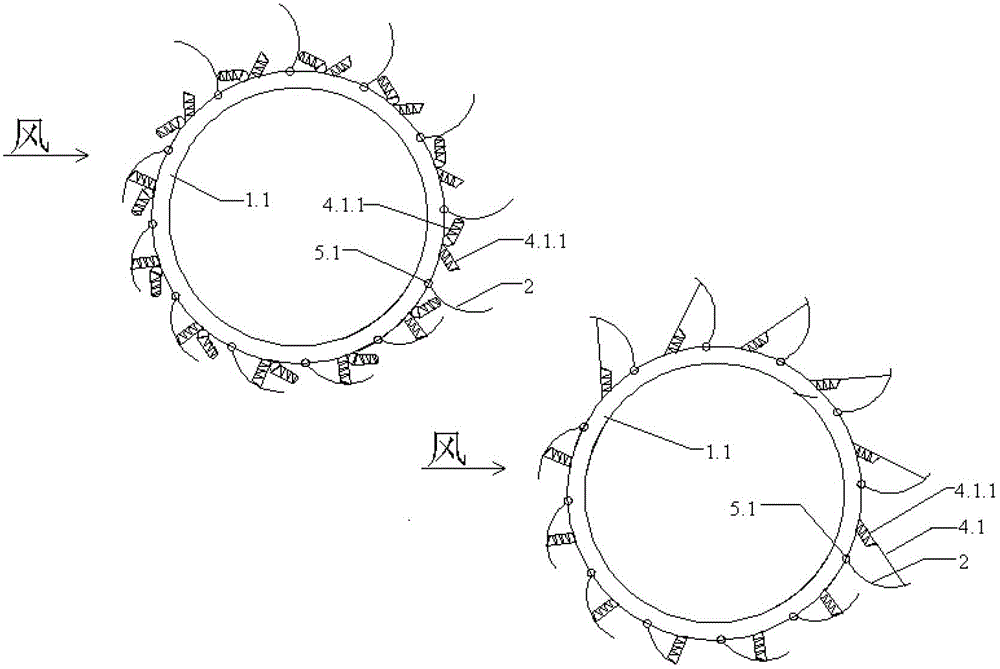
[0184]The fins are either inside the ring, or outside the ring, or above the ring, or below the ring, or inside the cavity of the ring support. The fins can be arranged equidistantly on one of the five circles such as the inner, outer, upper, lower, or inside of the cavity, or two, three, or four of the five circles Or five fins are provided at the same time, and the fins respectively arranged on different circumferences can not be connected into pieces, or can be connected into one large fin, thereby forming a semi-enclosed shape for the frame cavity of the ring bracket, or Form an almost full enclosure (just leave a little gap for the bracket of the rail car to pass through, such as Figure 20 , fins in Figure I). Some unloading wing rings for special purposes can even connect the fins at five positions into one piece (such as Figure 9 fins in 2).

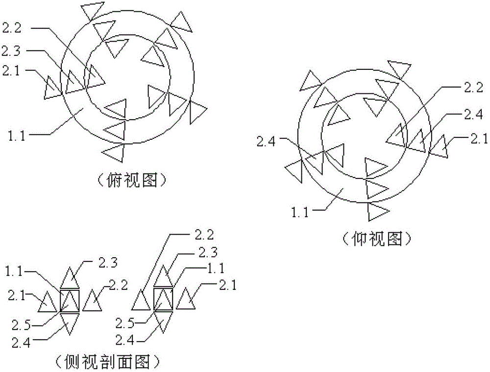
[0185] Example 2 (eg figure 2 , image 3 ):

[0186] Each wing 2 is connected wit...

example 3

[0189] Example 3 (such as figure 2 ):

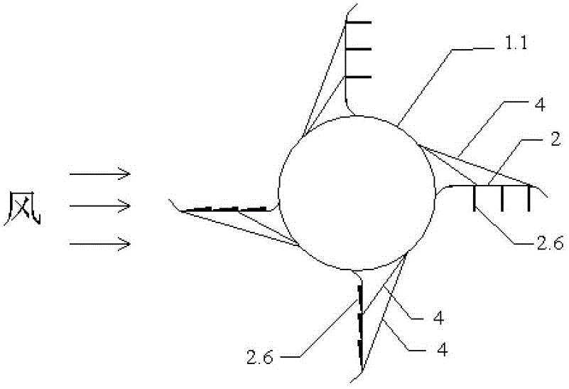
[0190] select Figure 4 In the E-shaped fin, the root of the fin is connected to the ring bracket of the wing ring, the upper end of the fin skeleton is connected to one end of the connecting rod 4, the other end of the connecting rod 4 is connected to the ring bracket 1.1, and the connecting rod 4 and the fin skeleton form a triangle. The E-shaped fin has a non-deformable skeleton, and the skeleton can be made of hard material or soft cloth; the corresponding position of the discharge port cover 2.6 of the E-shaped fin is the discharge port. The discharge outlet is like a window, and the discharge outlet is equipped with a door that is like a window.

[0191] Example 4 (such as Figure 5 ):

[0192] Each of the above embodiments and all unloading wing rings, all all unloading fins on the same annular support, its receiving flow surface (side for driving) all faces the same circular motion direction, and its unloading surface (side...

example 2

[0207] Example 2 (eg Figure 8 ):

[0208] The method and steps of building a large tower by layered assembly and layer-by-layer heightening are as follows:

[0209] Such as Figure 8 In the left figure, a plurality of (such as 30 to 50) pillars or small towers 4.2 with suitable heights (such as 100 meters) are erected equidistantly on the bottom ring support 1.1, and then along each pillar or small towers 4.2 A ring-shaped bracket 1.1 (or a ring-shaped regular polygonal beam frame) is erected on the top of the upper layer, so that each pillar or small tower frame is connected as a whole, so that they can support and reinforce each other. If it is necessary to further strengthen, the non-adjacent pillars or small towers 4.2 can be connected with a straight beam frame according to a fixed rule (such as Figure 8 shown on the right). This forms the first floor of the large pylon.

[0210] If the small tower 5.1 still cannot be hoisted by a helicopter, it can be disassembled...


PUM


Abstract

The invention discloses a loading/unloading wing ring, a loading/unloading wing ring mechanism, and a power generator, a water activator and a water activating method thereof. The loading/unloading wing ring and the loading/unloading wing ring mechanism are formed by engagement of a loading/unloading-type wing plate and a ring-shaped support. The wing plate of the mechanism is extremely light but huge in size and strong in wind-receiving capacity, so that the power-generating capacity of the large-size single machine exceeds that of a steam turbine generator. The mechanism can be built on a high tower of more than 500 meters, or suspends in the air instead of the high tower to form a suspended large-size wind turbine generator, or directly floats on the water surface to form an overwater wind turbine generator or a wind-powered aeration water activator for aquiculture. The vertical loading/unloading wing ring mechanism can receive wind from all directions and works without needing a steering mechanism. The loading/unloading wing ring mechanism can be set at the top of a building or can suspend in the air in combination with a floating-type support, is connected with the ground through multiple traction cables extending in different directions and suspends in the air above an open space, and serves as an overhead wind power station integrating the functions of power generation, communication, sun shading, rain shield and decoration.

Description

technical field [0001] The unloading wing ring belongs to a wind wheel or a water wheel, and the wings surround the center of the circle. [0002] The unloading wing ring mechanism belongs to a wind wheel mechanism or a water wheel mechanism, and the wings can rotate around the center of the circle. Wind or water wheel mechanisms either have only one rotor, or have two or more rotors. The combination of the wind wheel or water wheel mechanism and the generator can become a wind turbine generator or a water wheel generator. Background technique [0003] Human beings are eager to completely replace thermal power and nuclear power with wind power, so various wind power mechanisms have been invented, among which wind turbine generators are the most widely used. At present, wind turbine generators are mainly tower models located on the ground or on the sea. . [0004] The tower model must rely on the height of the tower to make the wind rotor obtain higher wind power, because ...

Claims


Application Information

Patent Timeline
IPC IPC(8): F03D3/06F03D9/00F03D11/00F03B3/12F03B13/00F03B11/00F03D9/25F03D9/45
CPCY02E10/226Y02B10/70Y02E10/223Y02E10/74Y02B10/30Y02E10/20
Inventor 罗琮贵
Owner 罗琮贵
Why Eureka
Try Eureka