Energy-efficient ceramic kiln burner

A ceramic kiln, high-efficiency and energy-saving technology, applied in burners, gas fuel burners, combustion methods, etc., can solve problems such as insufficient mixing, heat loss, unevenness, etc.

Inactive Publication Date: 2012-10-10
北京中宇先创能源科技有限公司
View PDF6 Cites 9 Cited by
  • Summary
  • Abstract
  • Description
  • Claims
  • Application Information

AI Technical Summary

Problems solved by technology

The main structure of the ceramic kiln burner includes a gas pipeline and an air supply pipeline. The air supply mode is natural ventilation or power distribution. The nozzle of the existing ceramic kiln burner air supply pipeline is set in parallel with the nozzle of the gas pipeline or communicated in the combustion head. , the gas and air are ejected from the nozzles at the front ends of the respective pipes, and the gas and air are mixed outside the combustion head, which is called post-mixing. The main disadvantages of this structure are that the mixing is insufficient and uneven, and the precise ratio cannot be achieved. (The optimal ratio of gas and wind α=1~1.1), so that when the air is insufficient, the excess gas is decomposed into carbon, hydrogen, carbon monoxide, carbon dioxide and nitrogen oxides, the gas utilization rate is low, and a large amount of harmful gas emissions are produced; when When the air is excessive, it will take away heat and cause heat loss

Method used


Image

  • Energy-efficient ceramic kiln burner

Examples


Embodiment Construction

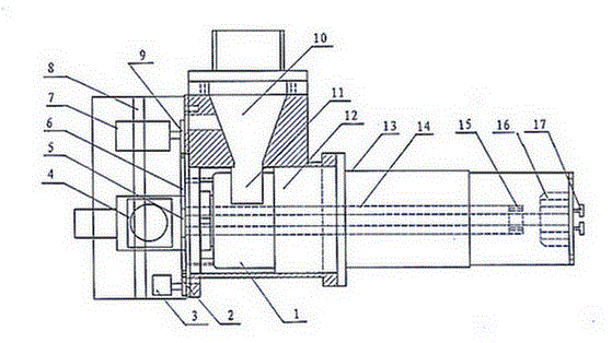
[0007] As shown in the attached figure, an air inlet chamber and an air outlet chamber form the base of the burner. There is a vent between the air inlet chamber and the air outlet chamber. The air supply pipe is connected to the air inlet chamber through the interface, and the air outlet chamber is cylindrical. The cylindrical shell is sealed with the flange of the air outlet chamber. The cylindrical shell forms the air supply pipe. The gas pipe is located in the cylindrical shell. The gas valve is connected to the rear end of the gas pipe. At the bottom of the combustion head, the front end of the gas nozzle is 20mm away from the bottom of the cup-shaped combustion head. An annular vent control baffle with a bottom plate is installed in the air outlet chamber. There is a bar-shaped air outlet on the baffle, and there is a rotating shaft in the middle of the bottom plate of the baffle. The rotating shaft passes through the wall of the air outlet chamber. A transmission gear is...


PUM


Abstract

The invention discloses an energy-efficient ceramic kiln burner. A base consists of an air intake chamber and an air outlet chamber, a cylindrical shell is connected with the air outlet chamber in a sealing manner, a cup-shaped burning head is fixed at the front end of the cylindrical shell in a sealing manner, a gas pipeline is arranged in the cylindrical shell, and a gas nozzle at the front end of the gas pipeline is aligned to the bottom of the cup-shaped burning head. The gas nozzle is arranged at the rear end of the burner and keeps a certain distance from the burning head, so that gas and air are premixed at the rear end of the burning head and form mixing concentration gradient, thereby effectively eradicating the backfire detonation phenomenon due to uniform mixing of the air and the gas in the cylindrical shell. The energy-efficient ceramic kiln burner automatically controls an air volume through a circuit to reach the best ratio of the gas to the air, can save above 20% of the gas than the existing burner, and has huge social and economical benefits of energy conservation, emission reduction, low carbon and environment friendliness.

Description

technical field [0001] The invention relates to a burner for an industrial kiln using combustible gas as fuel. Background technique [0002] The burner is the core component that provides heat energy to the ceramic kiln. The gas is injected into the kiln by the burner nozzle to burn to make the temperature in the kiln reach more than a thousand degrees. A ceramic kiln is equipped with dozens or hundreds of burners depending on its length. The combustion status of the burner is the key to the energy saving of the ceramic kiln. The main structure of the ceramic kiln burner includes a gas pipeline and an air supply pipeline. The air supply mode is natural ventilation or power distribution. The nozzle of the existing ceramic kiln burner air supply pipeline is set in parallel with the nozzle of the gas pipeline or communicated in the combustion head. , the gas and air are ejected from the nozzles at the front ends of the respective pipes, and the gas and air are mixed outside th...

Claims


Application Information

Patent Timeline
Patent Type & Authority Applications(China)
IPC IPC(8): F23D14/02F23D14/60F23D14/46
Inventor 穆瑞力
Owner 北京中宇先创能源科技有限公司
Why Eureka
Try Eureka