Rotating transformer position measuring system and method

A technology of resolver and measurement system, applied in the field of resolver, can solve the problems of increased system cost, difficult to stabilize the system, large amount of computation, etc., and achieves fast and accurate tracking of position signals, good static and dynamic performance, and low computing resource occupation. Effect

Active Publication Date: 2012-10-10
TONGJI UNIV
View PDF6 Cites 34 Cited by
  • Summary
  • Abstract
  • Description
  • Claims
  • Application Information

AI Technical Summary

Problems solved by technology

However, the entire algorithm is relatively complex, with a large amount of calculation, and the arctangent operation is very sensitive to the interference of the input signal. Once the input signal fluctuates slightly, the output will have a large deviation, and the entire system is difficult to stabilize.
[0007] A paper "Design of a High-Precision, Low-Cost Resolver Signal Solver" on the magazine "Micro and Special Motors" used the look-up table method to deal with the calculation of the arctangent function, which simplified the calculation process, but increased the DSP chip storage space requirements
[0008] At the same time, a master's thesis of Chongqing University, "FPGA-Based Resolver Decoding Algorithm and System Design", used the hardware resources of FPGA to perform arctangent calculation. Its advantage is that the calculation speed is fast, but the cost of the system is greatly increased by using FPGA.
[0009] It can be seen from the above three documents that most of the current resolver software decoding algorithms use the method of calculating the arctangent function, which inevitably brings about the problem of poor anti-interference

Method used


Image

  • Rotating transformer position measuring system and method
  • Rotating transformer position measuring system and method
  • Rotating transformer position measuring system and method

Examples


Embodiment Construction

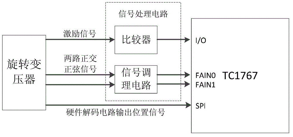
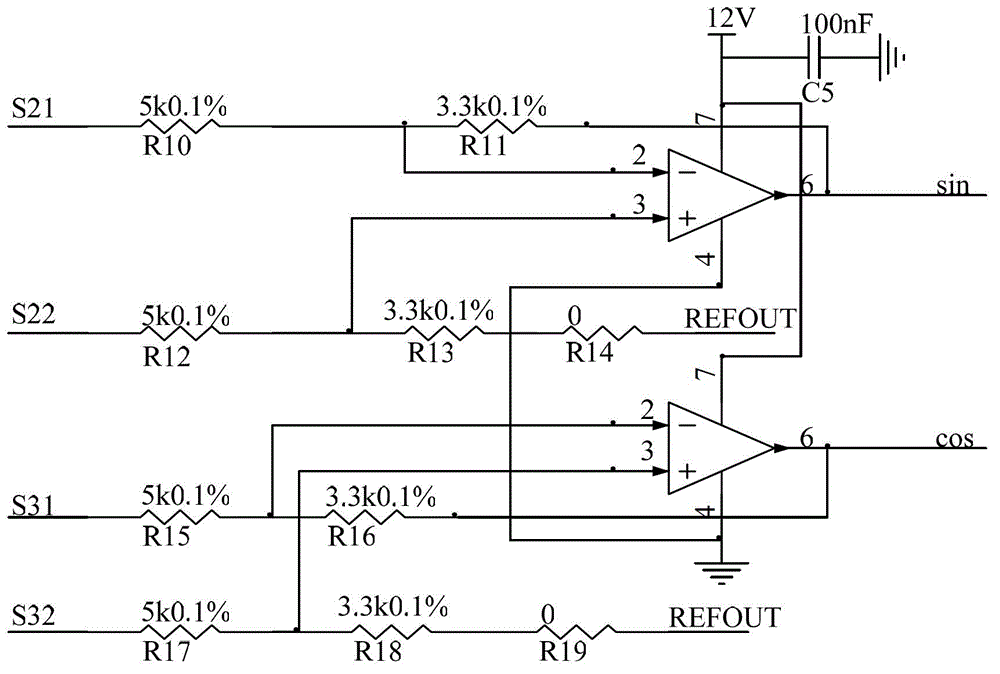
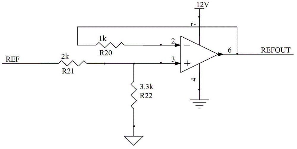
[0036] like figure 1 As shown, the rotary transformer position measurement system of the present invention includes: a signal processing circuit, a hardware decoding circuit and a single-chip microcomputer; the rotary transformer outputs the excitation signal and two-way orthogonal sinusoidal signals, and is input to the I / O of the single-chip microcomputer respectively through the processing of the signal processing circuit. O port and two input channels FAIN0 and FAIN1 of the fast A / D sampling module, and send the position signal output by the hardware decoding circuit to the microcontroller through the SPI communication interface. The single-chip microcomputer processes all input signals to ensure the stable operation of the measurement system.

[0037] The control chip designed in the present invention adopts the Infineon TriCore series single-chip microcomputer TC1767, and the sampling frequency of the fast A / D sampling module (FADC) integrated in the chip can be as high ...


PUM


Abstract

The invention discloses a rotating transformer position measuring system. The system comprises a signal processing circuit, a hardware decoding circuit and a singlechip, wherein the signal processing circuit is electrically connected with a rotating transformer and the singlechip, and is used for receiving and processing an excitation signal of the rotating transformer and two channels of orthogonal sinusoidal signals and outputting the signals to an input / output (I / O) port of the singlechip and two input channels of a quick analog / digital (A / D) sampling module; and the hardware decoding circuit is electrically connected with the rotating transformer and the singlechip, and is used for decoding rotating transformer position information and generating and outputting a position signal to a serial peripheral interface (SPI) communication interface of the singlechip. The quick A / D sampling function of the singlechip is used, the two channels of orthogonal sinusoidal signals of a secondary coil of the rotating transformer are acquired by the singlechip, the rest part of signal processing is finished in the singlechip through programming, and the redundancy function of the system can be realized by only a few peripheral circuits, so that the reliability of the system is greatly improved.

Description

technical field [0001] The invention relates to the technical field of rotary transformers, in particular to a measuring system and method for obtaining position information of rotary transformers through software decoding. Background technique [0002] As an angular position sensor, the resolver is widely used in various motion servo control systems, such as household appliances, industrial production processes, and electric vehicles, due to its high reliability and high precision. [0003] Since the signal directly output by the resolver is two orthogonal sinusoidal signals, it cannot be directly used to obtain the position information, but needs to be decoded to obtain the position information. Traditional resolvers mainly use hardware decoding circuits and dedicated decoding chips. Once the decoding circuit fails, the entire system cannot work normally, which reduces the reliability of the resolver position measurement system. [0004] At present, the patents on resolve...

Claims


Application Information

Patent Timeline
Patent Type & Authority Applications(China)
IPC IPC(8): G01B7/30
Inventor 朱元吴志红干瑞王双全陆科孙蔚武四辈刘习才沈琛驰李翔宇江涛王鹏袁黎君朱磊
Owner TONGJI UNIV
Why Eureka
Try Eureka