
Method and device for high-speed and accurate measurement of tunnel section

A technology of precise measurement and measuring devices, which is applied in measuring devices, section drawing, and optical devices, etc., can solve the problems of high measurement accuracy and sampling rate, and achieve the effects of reducing image processing load, compact structure, and improving accuracy

Active Publication Date: 2012-10-10
BEIJING JIAOTONG UNIV
View PDF6 Cites 28 Cited by
  • Summary
  • Abstract
  • Description
  • Claims
  • Application Information

AI Technical Summary

Problems solved by technology

Therefore, the existing tunnel section detection technology at home and abroad cannot guarantee high measurement accuracy and high sampling rate at the same time under the condition of high-speed dynamic measurement.

Method used


Image

  • Method and device for high-speed and accurate measurement of tunnel section
  • Method and device for high-speed and accurate measurement of tunnel section
  • Method and device for high-speed and accurate measurement of tunnel section

Examples


Embodiment 1

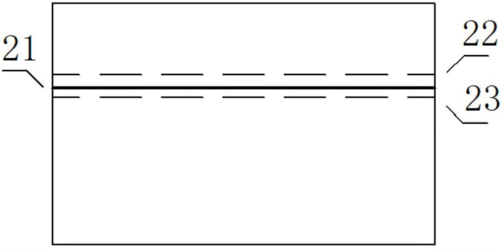
[0019] The present invention is mainly equipped on the railway inspection car, and the system starts to work when the inspection car passes through the tunnel. The laser scanning ranging system consists of two German SICK laser ranging sensors, which update the target distance in real time at a frequency of 35 frames per second, with an accuracy of 10mm. During the operation of the device, when the laser scanning ranging sensor detects that the target outline is assumed to be around a radius of 3m, this information is uploaded to the computer, and the computer calculates the spatial height of 3m corresponding to the camera at the corresponding angle of the photogrammetry system based on the pre-calibrated model. Near line 286 on the acquisition image, such as figure 2 Middle 21, while the target radius of 0.5m corresponds to the vicinity of the 240th and 317th lines of the image, such as figure 2 Middle 22 and 23. Then, the computer instructs the corresponding camera of th...

Embodiment 2

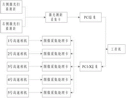
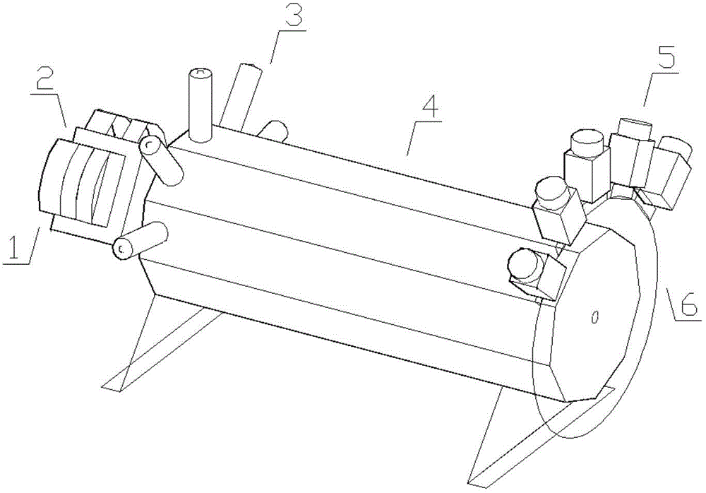
[0021] The whole measurement device is composed of three parts, (1) rough measurement module mainly composed of two laser scanning rangefinders; (2) photogrammetry module composed of multiple lasers and multiple high-speed industrial cameras; (3) data processing The system includes a plurality of image processing cards with FPGA as the processing core, a laser ranging acquisition card and a computer.

[0022] The laser ranging acquisition card collects the data of the laser scanning rangefinder and uploads it to the industrial computer, and the image processing card completes the image acquisition and model calculation functions of the camera, and corresponds to the camera one by one, such as image 3 shown. All the acquisition cards are connected with the industrial computer through the PCI bus. The image processing card performs multi-stage filtering on the image in the window and extracts the sub-pixel center of the light band by means of hardware circuit implementation, a...


PUM


Abstract

The invention discloses a method and a device for high-speed and accurate measurement of a tunnel section. The method comprises the steps as follows: overlapping a plurality of linear lasers end to end so as to obtain a large-angle tunnel section; synchronously acquiring laser profiles by a plurality of high-speed cameras, and carrying out image processing on the laser profiles; and carrying out model calculation from image coordinates to space coordinates so as to obtain a real coordinate of the tunnel section. The device comprises a laser scanning and distance measuring module, a photography measurement module and a data acquiring and processing module. According to the invention, the laser scanning and distance measuring technology and the photogrammetric triangulation technology are combined, the problem of difficultly processed data due to large data quantity in high-speed dynamic detection is solved, and the measurement requirements of high speed and high precision are satisfied. In addition, the device has the characteristics of compact structure and convenience in mounting and measurement.

Description

technical field [0001] The invention belongs to a tunnel geometric profile measurement method and equipment thereof. In particular, it relates to a high-speed and precise measurement method and device for a tunnel section. Background technique [0002] Due to factors such as train impact, geological deformation, nearby construction and line maintenance, the tunnel body is often deformed, seriously affecting operational safety. Therefore, the dynamic detection technology of the full section of the tunnel and the deformation of the cave body has always been one of the core technologies related to the safety of rail transit operation. [0003] At present, the dynamic detection technology at home and abroad mainly includes laser-assisted triangular photogrammetry technology and laser scanning measurement technology based on the principle of light propagation time. Both measurement principles have their own advantages and disadvantages. Although laser scanning measurement is n...

Claims


Application Information

Patent Timeline
Patent Type & Authority Applications(China)
IPC IPC(8): G01B11/00G01B11/24G01C7/06
Inventor 余祖俊朱力强郭保青郭一诗
Owner BEIJING JIAOTONG UNIV
Learn More