Solar simulator for testing solar cells

A technology of solar cells and solar simulators, applied in the field of solar simulators, can solve the problems of complex arrangement, difficult manufacturing, high cost, etc., and achieve the solution of uneven distribution of irradiance, inconsistency and convenience of irradiance , the effect of using a reasonable amount

Inactive Publication Date: 2012-10-10
SHEN ZHEN TRONY SCI & TECH DEV CO LTD
View PDF11 Cites 16 Cited by
  • Summary
  • Abstract
  • Description
  • Claims
  • Application Information

AI Technical Summary

Problems solved by technology

[0002] At present, the quality of the solar simulator used to test solar cells mainly depends on the irradiance intensity and uniformity of the light source. Among the light sources, the closest to sunlight is the xenon lamp, but the xenon lamp is a point light source, and the light source needs to be processed to be parallel and uniform. For example, Chinese patent 201020177252.9 "Reflective Solar Simulator" discloses a light source of xenon lamp that is processed into a uniform light source through reflection, but the reflection structure is relatively complicated, and the accuracy of the reflection device is high, and the calculation needs to be accurate. Manufacturing High difficulty
With the development of LED technology, people began to use LED as the light source of solar simulators. For example, Chinese patent 200810025522.1 "LED solar simulator" uses LEDs of various colors. The light intensity of the band can simulate the solar spectrum, but because LEDs are monochromatic light, it is necessary to optically mix LEDs of different colors to simulate the composite light of the solar spectrum, so a lot of light sources are required, and a set of light source composite system and light source are required The correction system has a complex structure and high cost. At the same time, due to the heating problem of the LED, it is easy to cause damage to the LED, so that the light source needs to be readjusted, which is inconvenient to use.
Chinese patent 201010291865.X "A multi-mirror and multi-fiber coupling solar light simulator light source" utilizes point light sources to emit light in a three-dimensional space and has the characteristics of a wide light-emitting angle. Realize high-efficiency utilization and output of light source energy, but the number of lenses is large, the arrangement is complicated, the floor area is large, and the cost is high

Method used


Image

  • Solar simulator for testing solar cells
  • Solar simulator for testing solar cells
  • Solar simulator for testing solar cells

Examples


Embodiment 1

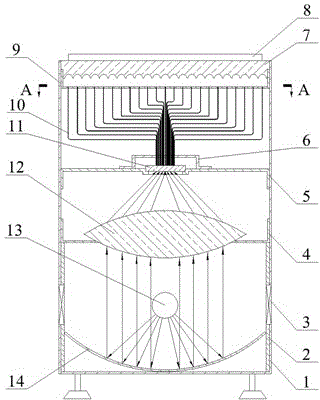
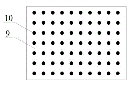
[0022] See Figure 1 to Figure 3 , a solar simulator for testing solar cells, which consists of a light source box, an optical system and a test platform. The light source box 1 is equipped with a plane reflector 2, an exhaust fan 3, a convex lens support plate 4, an optical filter support plate 5 and optical fiber fixing Board 6, the optical system is made up of xenon lamp 13, curved reflector 14, convex lens 12, optical filter 11, optical fiber bundle 10 and baffle plate 9, and the test platform is made of light-transmitting glass with grooves, each groove and The corresponding fiber points or fiber strips in the fiber bundle correspond, the other side of the test platform is a plane for placing solar cells, the arc reflector 14 is placed at the bottom of the light source box 1, and a light source xenon lamp 13 and a convex lens are installed at its focal point 12 is fixed by the support plate 4, and the converging end of the convex lens is equipped with an optical filter 11...

Embodiment 2

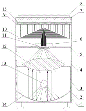
[0025] This embodiment is a solar simulator suitable for testing small-scale solar cells, see Figure 4 , the test platform is a split type, mainly composed of two pieces of glass, one of which is a flat glass for placing the solar cell 8, and the other glass has a groove, and the side with the groove is installed on the baffle on the top of the light source box 1 9, each groove corresponds to the corresponding fiber point or fiber strip in the fiber bundle, making the light irradiated on the test platform more uniform. The split structure of the test platform is more convenient to use, because when the solar cells are placed on the flat glass, the surface of the flat glass will be worn and needs to be replaced frequently. This split structure is more convenient to replace the glass on which the solar cells are placed, and can reduce costs. The structure and working principle of the solar simulator used to test solar cells in this embodiment are the same as those in Embodiment...

Embodiment 3

[0027] This embodiment is a solar simulator suitable for testing large-scale solar cells, see Figure 5 , the light source box 1 is equipped with a plurality of xenon lamps 13 and multiple sets of optical systems, which can be expanded horizontally and vertically according to needs. On the battery test platform, the test of large-scale solar cells is realized. The structure and working principle of the solar simulator used to test solar cells in this embodiment are the same as those in Embodiment 1, and will not be repeated here.


PUM


Abstract

The invention relates to a solar simulator, particularly relates to a solar simulator for testing solar cells, and belongs to the technical field of detection for solar cells. The solar simulator realizes that a light source is changed into a surface light source irradiating uniformly. The solar simulator is mainly technically characterized by comprising a light guide component, one end of the light guide component is an input end of a fiber bundle and is connected with a light filter, the other end of the light guide component is a fiber output end and is connected with a baffle on the top of a light source box, a solar cell testing platform is mounted above the baffle, a light receiving surface of the platform is provided with a groove corresponding to an output port of the fiber bundle, and light of a light source is condensed to the light filter from a convex lens, and is uniformly transmitted to the solar cell testing platform via the fiber bundle. The solar simulator is provided with a xenon lamp, the light of the light source is focused at first and then is uniformly scattered on the testing platform by fiber light guide technology, and the requirement on uniform and stable irradiation for testing electric performances of the solar cells is met.

Description

technical field [0001] The invention relates to a solar simulator, in particular to a solar simulator for testing solar cells, and belongs to the technical field of solar cell testing devices. Background technique [0002] At present, the quality of the solar simulator used to test solar cells mainly depends on the irradiance intensity and uniformity of the light source. Among the light sources, the closest to sunlight is the xenon lamp, but the xenon lamp is a point light source, and the light source needs to be processed to be parallel and uniform. For example, Chinese patent 201020177252.9 "Reflective Solar Simulator" discloses a light source of xenon lamp that is processed into a uniform light source through reflection, but the reflection structure is relatively complicated, and the accuracy of the reflection device is high, and the calculation needs to be accurate. Manufacturing High difficulty. With the development of LED technology, people began to use LED as the lig...

Claims


Application Information

Patent Timeline
Patent Type & Authority Applications(China)
IPC IPC(8): G01R1/28G01R31/26H02S50/10
CPCY02E10/50
Inventor 王付然李毅
Owner SHEN ZHEN TRONY SCI & TECH DEV CO LTD
Why Eureka
Try Eureka