Balanced type photoelectric detector in 2mu m coherent laser wind-finding radar system

A photoelectric detector and wind radar technology, which is applied in the field of photoelectric detectors, can solve the problems of many analog devices, high cost, and thermal noise of analog devices, and achieve the effects of reducing thermal noise, eliminating amplitude noise, and reducing costs

Inactive Publication Date: 2012-10-10
HARBIN INST OF TECH
View PDF4 Cites 13 Cited by
  • Summary
  • Abstract
  • Description
  • Claims
  • Application Information

AI Technical Summary

Problems solved by technology

[0020] The purpose of the present invention is to solve the problem of thermal noise caused by the high cost and thermal noise of the balanced heterodyne photodetector in the 2μm coherent laser wind radar system. The present invention provides a 2μm coherent Balanced Photoelectric Detector in Laser Wind Radar System

Method used


Image

  • Balanced type photoelectric detector in 2mu m coherent laser wind-finding radar system
  • Balanced type photoelectric detector in 2mu m coherent laser wind-finding radar system
  • Balanced type photoelectric detector in 2mu m coherent laser wind-finding radar system

Examples


specific Embodiment approach 1

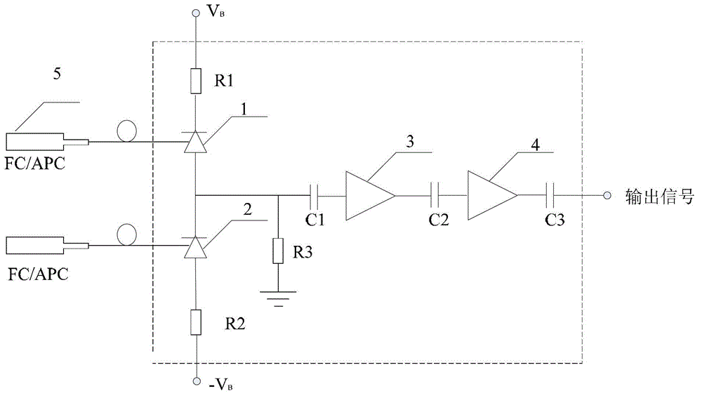
[0030] Specific implementation mode one: the following combination Figure 2 to Figure 7 In this embodiment, the balanced photodetector in the 2 μm coherent laser wind radar system includes a first PIN photodiode 1, a second PIN photodiode 2, a resistor R1, a resistor R2, a resistor R3, a capacitor C1, a capacitor C2, Capacitor C3, primary amplifier 3, secondary amplifier 4, the first FC / APC port 5 and the second FC / APC port 6; the signal light output port of the first FC / APC port 5 and the light of the first PIN photodiode 1 The signal receiving end is connected, the cathode of the first PIN photodiode 1 is connected to one end of the resistor R1, the other end of the resistor R1 is connected to the positive pole of the power supply, the local oscillator light output port of the second FC / APC port 6 is connected to the second PIN photoelectric The optical signal receiving end of the diode 2 is connected, the anode of the second PIN photodiode 2 is connected to one end of the ...

specific Embodiment approach 2

[0042] Embodiment 2: This embodiment is a further description of the balanced photodetector in the 2 μm coherent laser wind radar system described in Embodiment 1. The first PIN photodiode 1, the second PIN photodiode 2, and the resistor R1 , resistor R2, resistor R3, capacitor C1, capacitor C2, capacitor C3, primary amplifier 3 and secondary amplifier 4 are integrated in the microelectronic package.

[0043] The advantage of this package is that it can reduce the parasitic capacitance and increase the receiving bandwidth of the photodetector.

specific Embodiment approach 3

[0044] Embodiment 3: This embodiment is a further description of the balanced photodetector in the 2 μm coherent laser wind radar system described in Embodiment 1. The balanced photodetector is realized by InGaAs material.


PUM


Abstract

The invention discloses a balanced type photoelectric detector in a 2mu m coherent laser wind-finding radar system, which aims at solving the problems that in the 2mu m coherent laser wind-finding radar system, analog devices of the balanced type heterodyne photoelectric detector are multiple, so that no only is the cost high, but also heat noise is caused. Two PIN photoelectric diodes with almost completely same parameters are manufactured on one detection unit simultaneously. Incident signal light and local light are divided into two beams respectively through a beam splitter, are respectively guided into two reverse PIN tubes with matched parameters so as to carry out optical frequency mixing on light sensitive surfaces of two PIN photoelectric detectors, then generating heterodyne signals respectively, and outputting the balanced heterodyne intermediate-frequency signal by a two-stage amplifier after passing through a differentiator, wherein a capacitor C1, a capacitor C2 and a capacitor C3 play a role in filtering. The balanced type photoelectric detector disclosed by the invention is used for converting optical signals into electric signals.

Description

technical field [0001] The invention relates to a photoelectric detector, in particular to a balanced photoelectric detector in a 2 μm coherent laser wind radar system. Background technique [0002] At present, the balanced heterodyne detection technology is used to overcome the influence of the local oscillator light shot noise in the 2-m coherent laser wind radar system on the signal-to-noise ratio of the heterodyne detection. It can eliminate the optical noise of the local oscillator and improve the signal-to-noise ratio of the heterodyne signal. Its working principle is as follows figure 1 As shown, the balanced heterodyne receiving unit consists of two parallel detectors, and each detector has an independent photodiode (PIN), a low-noise preamplifier, a main amplifier and a band-pass filter. Signal light and local oscillator light are divided into upper and lower paths by beam splitter respectively. The signal light and the down path of the local oscillator light are ...

Claims


Application Information

Patent Timeline
Patent Type & Authority Applications(China)
IPC IPC(8): G01S7/48G01S17/95
CPCY02A90/10
Inventor 李彦超王春晖
Owner HARBIN INST OF TECH
Why Eureka
Try Eureka