Magnetic wave-absorbing structure loaded with pinpoint patch
A technology of magnetic wave absorption and wave structure, applied in the direction of electrical components, antennas, etc., can solve the problems of increasing the thickness of the absorber and demanding materials, and achieve the effect of expanding the absorbing frequency band, low cost, and simple process
- Summary
- Abstract
- Description
- Claims
- Application Information
AI Technical Summary
Problems solved by technology
Method used
Image

Examples
Embodiment 1
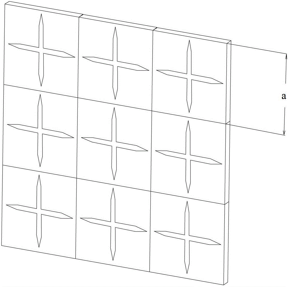
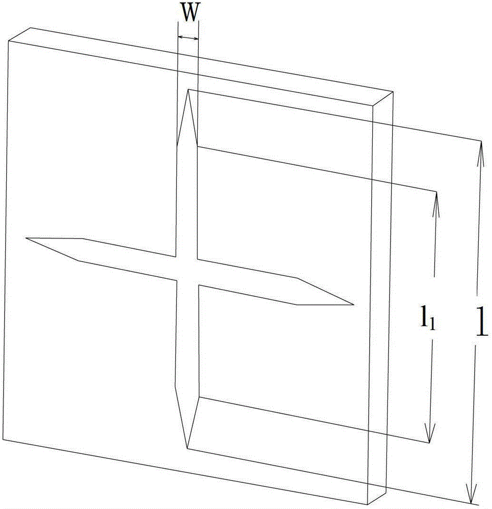
[0016] In this embodiment, a periodic aluminum foil pattern is loaded on the surface of a 3 mm thick wave-absorbing rubber sheet. Aluminum foil unit size a=33mm, l=30mm, l 1 =20mm, w=2mm.
[0017] Experiments show that the -10dB absorbing frequency band of this embodiment is 2GHz-4.64GHz under the condition of vertically incident TE or TM waves. For the 3mm thick absorbing rubber sheet without embedded periodic aluminum foil, the -10dB absorbing frequency range is 2.8GHz to 4.4GHz. In contrast, after loading the periodic dipole aluminum foil patch, its -10dB absorbing bandwidth is strengthened both in the high frequency band and the low frequency band, especially in the low frequency band.
Embodiment 2
[0019] In this embodiment, a periodic aluminum foil pattern is loaded on the surface of a 2.2 mm thick wave-absorbing rubber sheet. Aluminum foil unit size a=28mm, l=25mm, l 1 =19mm, w=2mm.
[0020] Experiments show that, in the case of vertically incident TE or TM waves in this embodiment, the -10dB absorbing frequency band is 2.0GHz-3.6GHz. The 2.2mm thick wave-absorbing rubber sheet not embedded with periodic aluminum foil has a -10dB wave-absorbing frequency range of 3.0GHz to 4.8GHz. In contrast, after loading the periodic dipole aluminum foil patch, its -10dB absorbing bandwidth obviously moves from high frequency to low frequency.
Embodiment 3
[0022] In this embodiment, a periodic aluminum foil pattern is loaded on the surface of a 2.2 mm thick wave-absorbing rubber sheet. Aluminum foil unit size a=28mm, l=25mm, l 1 =15mm, w=2mm.
[0023] Experiments show that the -10dB absorbing frequency range of this embodiment is 2.1GHz-3.9GHz under the condition of vertically incident TE or TM waves. The 2.2mm thick wave-absorbing rubber sheet not embedded with periodic aluminum foil has a -10dB wave-absorbing frequency range of 3.0GHz to 4.8GHz. In contrast, after loading the periodic dipole aluminum foil patch, its -10dB absorbing bandwidth obviously moves from high frequency to low frequency.
[0024] The description has fully explained the principle and necessary technical content of the present invention, and those of ordinary skill can implement the present invention according to the description, so more specific technical details will not be repeated.
PUM
 Abstract
Description
Claims
Application Information
 - R&D
- Intellectual Property
- Life Sciences
- Materials
- Tech Scout
- Unparalleled Data Quality
- Higher Quality Content
- 60% Fewer Hallucinations
Browse by: Latest US Patents, China's latest patents, Technical Efficacy Thesaurus, Application Domain, Technology Topic, Popular Technical Reports.
© 2025 PatSnap. All rights reserved.Legal|Privacy policy|Modern Slavery Act Transparency Statement|Sitemap|About US| Contact US: help@patsnap.com