Method and device for ultrasonic image space compound imaging

A space compounding and ultrasonic image technology, applied in the field of compound imaging, can solve the problems of compound image blurring, resolution reduction, image blurring, etc., and achieve the effects of reducing speckle noise, improving resolution, and improving clarity

Active Publication Date: 2012-10-17
EDAN INSTR
View PDF4 Cites 21 Cited by
  • Summary
  • Abstract
  • Description
  • Claims
  • Application Information

AI Technical Summary

Problems solved by technology

[0003] In the prior art, the patent publication number is: the Chinese patent of CN102038519A, which discloses a spatial composite imaging method for ultrasonic diagnosis. In the directional ultrasonic scanning, the beam signals of the transmitting and receiving channels are respectively processed by the window function, and then the obtained N original ultrasonic image data in different directions are processed by the histogram equalization algorithm or matching algorithm, and then the processed ultrasonic image data is processed. Spatial compound imaging to obtain the final ultrasound image; however, this method of spatial compound imaging is not suitable when the frame rate of ultrasonic scanning is low and the movement speed of human tissue is fast (that is, the motion property is high)
When performing spatial composite imaging on ultrasonic images, it is often required to scan human tissues through different scanning angles, and the actual positio

Method used


Image

  • Method and device for ultrasonic image space compound imaging
  • Method and device for ultrasonic image space compound imaging
  • Method and device for ultrasonic image space compound imaging

Examples


Embodiment Construction

[0025] In order to make the object, technical solution and advantages of the present invention clearer, the present invention will be further described in detail below in conjunction with the accompanying drawings and embodiments. It should be understood that the specific embodiments described here are only used to explain the present invention, not to limit the present invention.

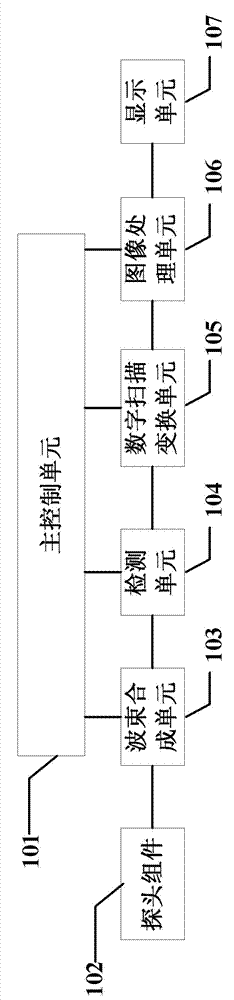
[0026] see figure 1 , a schematic diagram of the overall structure of an ultrasonic image spatial compound imaging according to the present invention, including a main control unit 101, a probe assembly 102, a beam forming unit 103, a detection unit 104, a digital scan conversion unit 105, an image processing unit 106 and a display unit 107. Its working process is as follows: the transmitter of the probe assembly 102 excites the probe elements to transmit ultrasonic waves to the human tissue, and then the array element group of the probe assembly 102 receives the ultrasonic echo signal reflected by...


PUM


Abstract

The invention discloses a method and a device for ultrasonic image space compound imaging. The method comprises the following steps of: receiving ultrasonic echo signals with different deflection angles; performing image space compound imaging for the ultrasonic echo signals with different deflection angles; calculating the variance of the image data after the present compound imaging with the image data after the previous compound imaging, and then getting the absolute value, so as to obtain the variance image data, comparing the variance image data with a preset variance threshold, and judging whether the image data with a high motion attribute exists in the image data after the present compound imaging; and determining the output mode of the image data according to whether the image data with a high motion attribute exists in the image data after the present compound imaging. In the technical scheme of the invention, different image processing modes can be chosen according to the judged image motion attribute by judging the image data with a high motion attribute; and speckle noise, sound shadow and reverberation in an ultrasonic image can be effectively reduced, thus improving the definition of the image.

Description

technical field [0001] The invention relates to a compound imaging method and device, in particular to a space compound imaging method and device for ultrasonic images. Background technique [0002] With the continuous development of science and technology, ultrasonic scanning diagnostic systems have been more and more widely used in medicine, and the application of spatial composite imaging technology can obtain ultrasonic echo information from different angles, thereby improving the image's edge detail performance and contrast. It also has a good effect on reducing speckle noise, sound shadow, reverberation, etc. in ultrasound images. [0003] In the prior art, the patent publication number is: the Chinese patent of CN102038519A, which discloses a spatial compound imaging method for ultrasonic diagnosis. The patent specifically uses the window function for the beam signals of the transmitting and receiving channels in ultrasonic scanning in N different directions. process...

Claims


Application Information

Patent Timeline
IPC IPC(8): A61B8/00G06T5/50
Inventor 覃伟和陈敏刘旺锋
Owner EDAN INSTR
Why Eureka
Try Eureka