Automatic expansion joint system and automatic expansion joint control method

An expansion joint and automatic technology, applied in the direction of heat exchange equipment, etc., can solve the problems affecting the quality of expansion joints, the production quality and production efficiency of shell and tube heat exchangers, etc., so as to improve the accuracy of expansion joints, improve production quality and Production efficiency and the effect of ensuring production safety

Active Publication Date: 2012-10-17
GREE ELECTRIC APPLIANCES INC +1
View PDF4 Cites 3 Cited by
  • Summary
  • Abstract
  • Description
  • Claims
  • Application Information

AI Technical Summary

Problems solved by technology

[0006] In view of this, the present invention provides an automatic expansion joint system and an automatic expansion joint control method to overcome the disadvantages of manual operation in the prior art and the f

Method used


Image

  • Automatic expansion joint system and automatic expansion joint control method
  • Automatic expansion joint system and automatic expansion joint control method
  • Automatic expansion joint system and automatic expansion joint control method

Examples


Embodiment 1

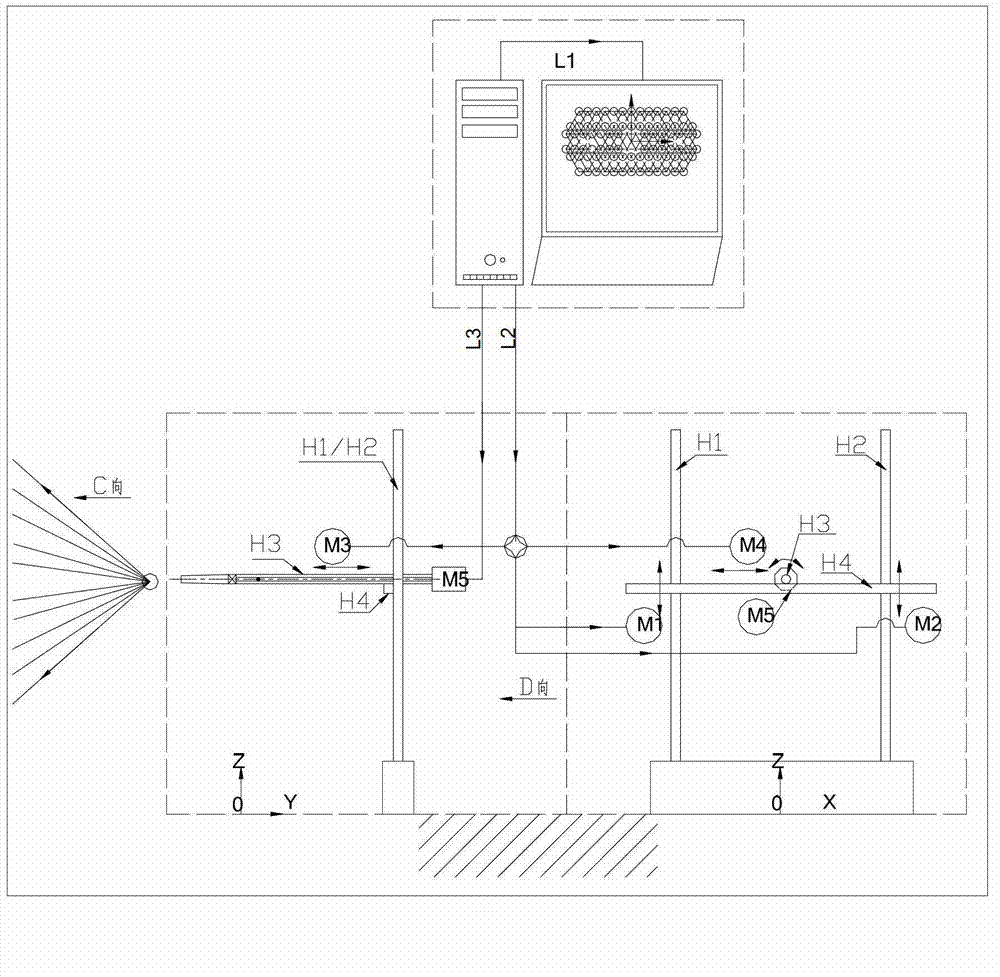
[0061] Please refer to the attached figure 1 , is a structural schematic diagram of an automatic expansion joint system disclosed in the present invention.

[0062] The automatic expansion system includes: a computer integrated control and display subsystem L1, a tube expander servo control subsystem L2 and a tube expander expansion control subsystem L3 respectively connected to the computer integrated control and display subsystem L1.

[0063] The computer integrated control and display subsystem L1 is the core of the entire automatic expansion joint system, which can store, display and print various expansion joint parameters. In addition, the subsystem is equipped with automatic control software, which can automatically control the servo control subsystem L2 of the tube expander and the tube expander Expansion joint control subsystem L3 action.

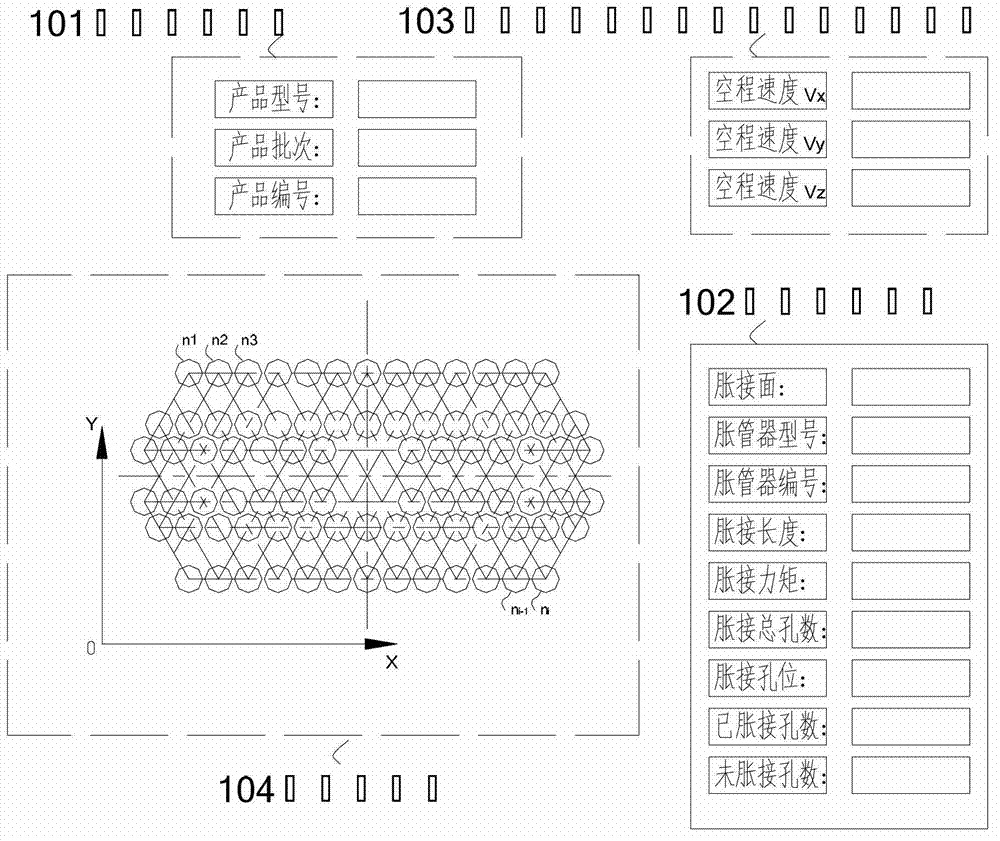
[0064] For clarification, please refer to the attached figure 2 , is the display interface of the computer integrated control...

Embodiment 2

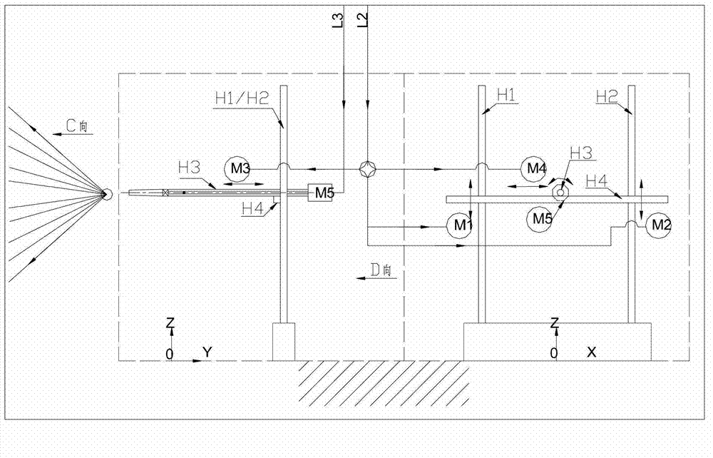
[0071] Please refer to the attached image 3 , is a specific structural diagram of the tube expander servo control subsystem L2 and the tube expander expansion control subsystem L3 in the automatic expansion joint system disclosed in the present invention.

[0072] The tube expander servo control subsystem L2 includes: a first shaft H1, a second shaft H2, a beam H4, a first drive M1, a second drive M2, a third drive M3 and a fourth drive M4, wherein:

[0073] The first axis H1 and the second axis H2 are perpendicular to the ground, the first axis H1 is connected to the first drive M1, the second axis H2 is connected to the second drive M2, and the first drive M1 and the second drive M2 synchronously control the main shaft of the tube expander to move up and down along the vertical direction of the first axis H1 and the second axis H2;

[0074] The main shaft of the tube expander is connected to the third drive M3, and the third drive M3 controls the main shaft of the tube exp...

Embodiment 3

[0084] Please refer to the attached Figure 4 , is a structural schematic diagram of another automatic expansion system disclosed in the present invention.

[0085] The automatic expansion system includes: computer integrated control and display subsystem L1, tube expander servo control subsystem L2 connected to the computer integrated control and display subsystem L1, tube expander expansion control subsystem L3 and self-lubricating Control subsystem L4.

[0086] Among them, the structure and function description of the computer integrated control and display subsystem L1 and the tube expander servo control subsystem L2 and tube expander expansion control subsystem L3 respectively connected to the computer integrated control and display subsystem L1 please refer to the implementation The relevant descriptions of Example 1 and Embodiment 2 will not be repeated here.

[0087] The self-lubrication control subsystem L4 controls the lubrication of the expanding head of the tube ...


PUM


Abstract

The invention discloses an automatic expansion joint system. A computer is integrated with a display control subsystem to store, display and print relative product information of a printing shell pipe type heat exchanger, expansion joint relative information, an expansion joint hole position image, and relative information of a pre-set expansion pipe machine servo control subsystem; and a pipe expansion machine expansion joint control subsystem and a pipe expansion machine servo control subsystem are controlled to move according to the expansion joint relative information and the relative information of the expansion pipe machine servo control subsystem. The invention also discloses an automatic expansion joint control method which comprises the following steps that: the computer is integrated with the display control subsystem to control the pipe expansion machine expansion joint control subsystem and the pipe expansion machine servo control subsystem to automatically carry out expansion joint, so that holes and heat exchange pipe bundles (which need to be subjected to the expansion joint) on the shell pipe type heat exchanger are jointed in an expansion manner. With the adoption of the system and the method disclosed by the invention, the manual operation is not needed, and the expansion joint quality and the production efficiency are improved.

Description

technical field [0001] The invention relates to the field of manufacturing shell-and-tube heat exchangers, and more specifically relates to an automatic expansion joint system and an automatic expansion joint control method. Background technique [0002] With the increasingly stringent regulations on fluid temperature in the process of various heat transfer equipment, there are more and more heat exchangers on the market that are used to transfer part of the heat of the hot fluid to the cold fluid to make the fluid temperature meet the requirements of the process. At present, the most widely used shell and tube heat exchanger is composed of shell, heat exchange tube bundle, tube sheet, baffle (baffle) and tube box. [0003] At present, in the manufacture of shell-and-tube heat exchangers, it is more common to use strength expansion as the connection method between the tube sheet and the heat exchange tube bundle. The strength expansion joint refers to the expansion joint th...

Claims


Application Information

Patent Timeline
IPC IPC(8): B21D39/00B21D53/08
Inventor 周艳彬陈建国王晓彬温彩凤封波
Owner GREE ELECTRIC APPLIANCES INC
Why Eureka
Try Eureka