Numerical control engraving and milling machine tool with linear motors

A linear motor, engraving and milling technology, applied in the direction of metal processing machinery parts, large fixed members, feeding devices, etc., can solve the problems of attenuation of positioning accuracy, low processing efficiency, low drag acceleration, etc., to reduce attenuation and improve processing High efficiency and high positioning accuracy

Inactive Publication Date: 2012-10-17
宁波市凯博数控机械有限公司
View PDF8 Cites 12 Cited by
  • Summary
  • Abstract
  • Description
  • Claims
  • Application Information

AI Technical Summary

Problems solved by technology

[0002] The prior art CNC engraving and milling machine tool uses a rotary servo motor plus a ball screw pair to drag the X, Y, and Z skateboard movements to realize three-dimensional seeking engraving and milling cutting processing. Because the rotary servo motor needs to use the ball screw pair to convert the rotary motion into dragging The linear reciprocating motion of the skateboard, the dragging speed is slow, and the dragging speed is less than or equal to 100 m/min; the dragging acceleration is low, and the maximum acceleration is 1.5g, resulting in slow three-dimensional homing speed of

Method used


Image

  • Numerical control engraving and milling machine tool with linear motors

Examples


Embodiment Construction

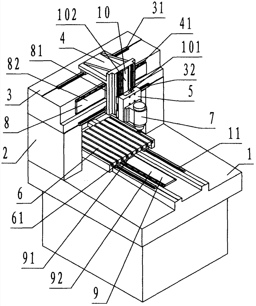
[0023] refer to figure 1 , a linear motor CNC engraving and milling machine tool of the present invention, comprising a bed 1, a column 2, a beam 3, an X-axis slide plate 4, a Z-axis slide plate 5, a workbench 6, a spindle motor 7, an X-axis linear motor 8, and a Y-axis Linear motor 9, Z-axis linear motor 10, wherein: the bed 1 is a hollow marble rectangular platform member, on the top of the bed 1, two parallel and upward The protruding cast iron slide rail is called the Y-axis slide rail 11;

[0024] The crossbeam 3 is a solid marble rectangular member, and the front and rear sides below the crossbeam 3 are respectively fixed and orthogonally connected with a vertically downward solid marble rectangular column 2, and the bottom of the column 2 is fixed and orthogonally connected to the bed 1. The front and rear sides on the left side of the top are fixedly connected by the bed 1, the column 2 and the beam 3 to form a marble gantry fixed body; The quality slide rail is call...


PUM


Abstract

The invention discloses a numerical control engraving and milling machine tool with linear motors, comprising a tool body (1), a vertical column (2), a cross beam (3), an X-axis sliding plate (4), a Z-axis sliding plate (5), a working platform (6), a main shaft motor (7), an X-axis linear motor (8), a Y-axis linear motor (9) and a Z-axis linear motor (10). The numerical control engraving and milling machine tool disclosed by the invention has the advantages that the technical scheme that the linear motors are used for dragging the X-axis sliding plate, the Y-axis sliding plate and the Z-axis sliding plate to carry out three-dimensional target-seeking engraving-milling cutting and machining is adopted, and the characteristics of the linear motors that the dragging speed is fast, the acceleration is high, the positioning accuracy is high, no wear attenuation is generated, no stroke length limitation exists are utilized, so that the defects that the dragging is realized by rotating a servo motor and adding a ball screw assembly is avoided, and the purposes of improving the target-seeking machining efficiency, alleviating the positioning accuracy attenuation and no limitation on the stroke length are achieved.

Description

technical field [0001] The invention relates to a numerically controlled engraving and milling machine tool, specifically a linear motor numerically controlled engraving and milling machine tool which is numerically controlled by a computer and driven by a linear servo motor for three-dimensional seeking engraving and milling. Background technique [0002] The prior art CNC engraving and milling machine tool uses a rotary servo motor plus a ball screw pair to drag the X, Y, and Z skateboard movements to realize three-dimensional seeking engraving and milling cutting processing. Because the rotary servo motor needs to use the ball screw pair to convert the rotary motion into dragging The linear reciprocating motion of the skateboard, the dragging speed is slow, and the dragging speed is less than or equal to 100 m / min; the dragging acceleration is low, and the maximum acceleration is 1.5g, resulting in slow three-dimensional homing speed of the machine tool and low processing ...

Claims


Application Information

Patent Timeline
IPC IPC(8): B23Q37/00B23Q1/01B23Q5/36
Inventor 李恒国沈良永胡庆东徐建国
Owner 宁波市凯博数控机械有限公司
Why Eureka
Try Eureka