Evaporation device

A technology of evaporation and evaporation source, applied in the direction of electrical components, electrical solid devices, circuits, etc., can solve the problems of damage, evaporation source failure, high cost, etc., and achieve the effect of low cost, prevention of looping, and difficulty in failure

Inactive Publication Date: 2012-10-17
HITACHI HIGH-TECH CORP
View PDF8 Cites 13 Cited by
  • Summary
  • Abstract
  • Description
  • Claims
  • Application Information

AI Technical Summary

Problems solved by technology

If Al enters into the heating chamber 10, there is a problem that the heater 3 and the reflector 4 are attached and reacted, and the heater 3 is deteriorated to cause a disconnection, or the insulator (not shown) supporting the heater 3 is damaged. Obstructions) accumulate and have conductivity, accumulate on the reflector 4, pass through the insulator with surface conductivity, cause the heater 3 and the reflector 4 (which is grounded at this time) to be electrically shorted, etc., and cause the evaporation source of the evaporation device to fail.
There is a problem that due to the upward creep of Al or the infiltration of Al vapor, Al adheres to the heater for heating or the insulator that supports the heater and should have electrical insulation, and an electrical short occurs, causing malfunction and damage to the evaporation source. s reason
In addition, in the crucible in which the crucible body and the nozzle are integrated, there is a problem of difficulty in manufacturing and high cost.

Method used


Image

  • Evaporation device
  • Evaporation device
  • Evaporation device

Examples


Embodiment 1

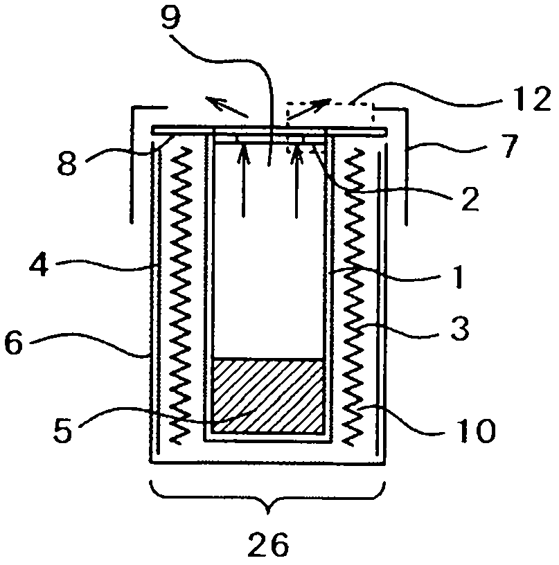
[0049] From Figure 1 to Figure 4 and Figure 17 is a diagram illustrating this embodiment. figure 1 It is a schematic sectional view of the evaporation source of the evaporation apparatus of this Example. Figure 17 It is a schematic sectional view of the evaporation source of the evaporation apparatus for comparison with Example 1. figure 2 It is an explanatory drawing of the crucible of the vapor deposition apparatus of Example 1. image 3 It is a schematic configuration diagram of a vapor deposition apparatus using the vapor deposition source of Example 1. FIG. Figure 4 It is a process diagram showing an example of an organic EL display production process.

[0050] First, in order to compare with Example 1, the Figure 17 The evaporation source of the evaporation device will be described. Figure 17 The evaporation source consists of a crucible (main body) 1 with a crucible flange 8, a heater (heating device) 3, a reflector 4, an evaporation material 5, an outer c...

Embodiment 2

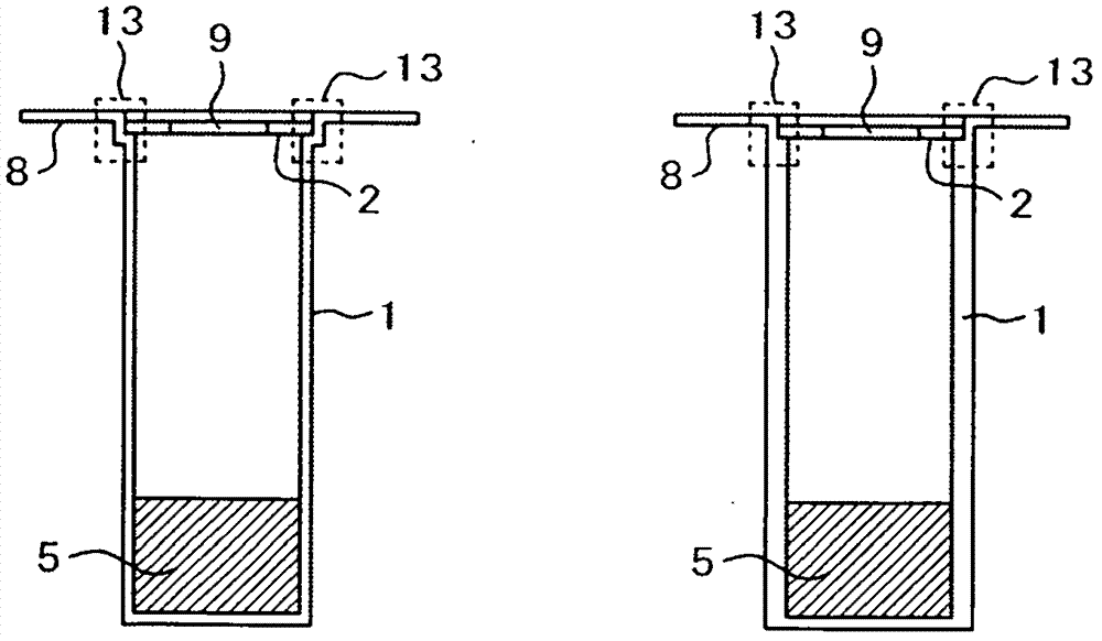
[0078] Figure 5 It is a schematic sectional view of the evaporation source of the evaporation apparatus of Example 2. exist figure 1 The reflector 4 shown in is omitted for simplicity. In the following drawings, the descriptions are also omitted within the scope that no particular description is required. Only for example 1 figure 1 The different sections are explained. The same applies to Examples after Example 3. This embodiment is characterized in that the structure 2 having the nozzle is exposed outward from the fixing member 7 , in other words, is exposed outward in the vertical direction with respect to the plane including the crucible flange 8 . In addition, the opening of the structure 2 having the nozzle is upward.

[0079] Since the structure 2 with the nozzle is outward from the fixing member 7, in other words, it is a structure exposed to the outside in the vertical direction relative to the plane including the crucible flange 8, therefore, the upward cree...

Embodiment 3

[0085] Figure 7 It is a schematic sectional view of the evaporation source of the evaporation apparatus of Example 3. This embodiment is characterized in that the structure 2 having the nozzle is exposed from the fixture 7 to the outside of the crucible 1 and the crucible flange 8 , and the opening 9 of the nozzle structure 2 faces the horizontal direction.

[0086] In this embodiment, too, the nozzle structure 2 is exposed from the fixture 7 to the outside of the crucible 1 and the crucible flange 8 , so that upward creep of Al is less likely to occur as the temperature of the crucible 1 decreases. Since the Al vapor has a cut 12 on the path from the nozzle to the heating chamber, it is also difficult for the Al vapor to go back to the heating chamber 10 .

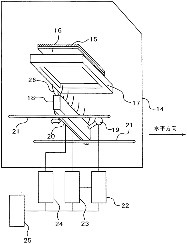
[0087] Figure 8 It is a schematic configuration diagram of the vapor deposition apparatus of Example 3. The evaporation source 18 composed of a plurality of vertical evaporation source units 26 arranged parallel to o...


PUM


Abstract

The utility model provides an evaporation device of an evaporation source which is easy to damage caused by the upward movement of Al or the immersion of the Al steam at a low cost. The evaporation device is provided with an evaporation source unit (26) in a vacuum chamber. The evaporation source unit (26) is provided with a crucible (1) which stores an evaporation material (5), a nozzle (2) arranged on an opening of the crucible (1), a heating chamber (10) surrounds the crucible (1) and stores a heater (3), and a fixing member (7). A cutting opening (12) is arranged between the inner wall of the crucible (1) and the above heating chamber (10). The cutting opening (12) prevents the evaporation material (5) melted in the crucible (1) or the steam of the evaporation material (5) from entering into the heating chamber (10).

Description

technical field [0001] The present invention relates to an apparatus for forming a vapor deposition film, and more particularly to an efficient vapor deposition apparatus for forming a thin film on a substrate by evaporating an evaporation material in a molten state. Background technique [0002] Currently, organic EL elements are actively being developed. An organic EL display (organic EL display device) is expected as a next-generation thin-film display to replace liquid crystals, plasma displays, and the like. Currently, organic EL displays are also being used in portable devices such as mobile phones and car stereos. In addition, the development of organic EL lighting catches up with the already commercialized LED lighting. In particular, since LED lighting emits almost point light, it is necessary to study the control of heat generation and the diffusion of light even if it is developed toward miniaturization. On the other hand, it can be considered that organic EL l...

Claims


Application Information

Patent Timeline
Patent Type & Authority Applications(China)
IPC IPC(8): C23C14/24
CPCC23C14/243C23C14/26
Inventor 山本健一三宅龙也玉腰武司松浦宏育峰川英明矢崎秋夫楠敏明尾方智彦
Owner HITACHI HIGH-TECH CORP
Why Eureka
Try Eureka