Friction damper

A friction damper and damper technology, applied in the field of shock, vibration, and earthquake control devices, can solve the problems of unstable damping performance, difficult assembly, limited displacement, etc., and achieve high stress and strain levels, high material utilization, and The effect of large preload displacement

Active Publication Date: 2012-10-17
QINGDAO CREATE ENVIRONMENT CONTROL TECH +1
View PDF9 Cites 28 Cited by
  • Summary
  • Abstract
  • Description
  • Claims
  • Application Information

AI Technical Summary

Problems solved by technology

At present, commonly used friction dampers are mainly divided into two categories: one category uses electromagnetic devices to control sliding friction, such as a magnetically controlled friction damper disclosed in patent application No. 018007365.4. This type of damper has a complex structure and requires certain Therefore, the cost and use cost are relatively high; the other type uses mechanical principles to control sliding friction. There are two types of friction dampers commonly used in the market: flat plate type and round tube type, such as the one disclosed in the patent application number 200810056406.6 A plate-type variable friction damper and a displacement linear friction damper disclosed in patent application number 200910210939.X
In the prior art, the flat-plate friction damper is mainly composed of a sliding plate and a splint, and then assembled and pressed by pre-tightening bolts and springs. Since the spring is used in the structure, the pre-tightening force is small, and it is difficult to achieve a large damping force output. , if you want to greatly increase the pre-tightening force, the space required by the spring is too large, and the practicability is poor. Using the pre-tightening bolt alone cannot kee...

Method used


Image

  • Friction damper
  • Friction damper
  • Friction damper

Examples


Embodiment 1

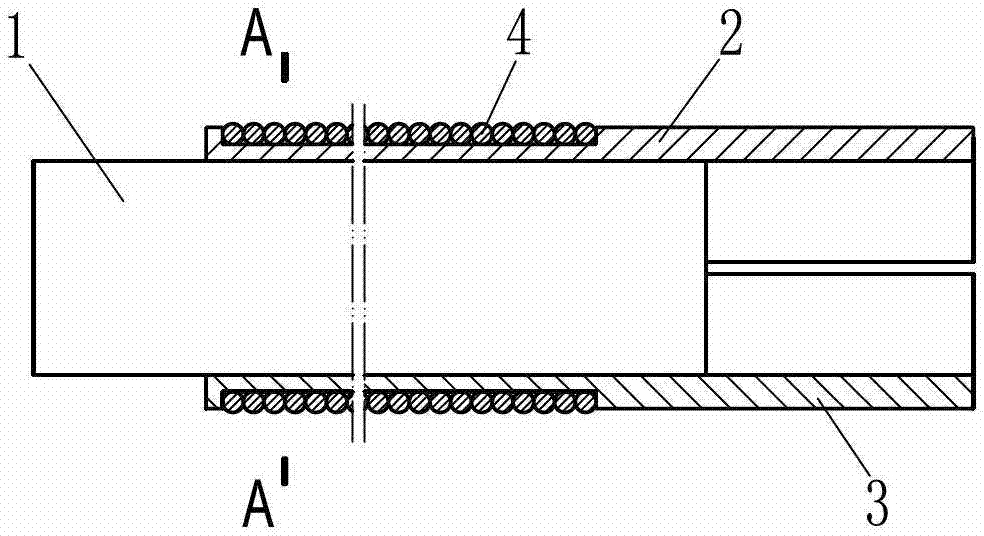
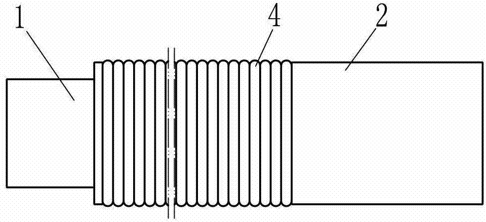
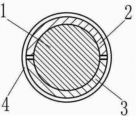
[0091] Such as figure 1 , figure 2 and image 3 The friction damper of the present invention shown includes a plunger 1 and a restraint cylinder, the restraint cylinder is composed of a sub-constraint cylinder 2 and a sub-constraint cylinder 3 along the axial direction of the plunger, and the plunger 1 is in close contact with the inner walls of the sub-constraint cylinders 2 and 3 , the outer surface of the restraint cylinder is provided with a tightening device, specifically the tightening device is a pre-tightening wire rope 4 partially wound on the outer surface of the sub-constraint cylinders 2 and 3, and the pre-tightening wire rope 4 is specifically a steel wire. It should be pointed out that the steel wire 4 The pre-tightening force is applied during the winding process of the surface of the restraining cylinder, and the pre-tightening force is maintained by the end fixing device of the steel wire (usually clamped with screws, not shown in the figure), so the steel w...

Embodiment 2

[0098] Such as Figure 5 , Figure 6 and Figure 7 The difference between the shown friction damper of the present invention and Embodiment 1 is that the limit device includes two limit stops 9 that are respectively fixedly welded on the outer surfaces of the steel sub-constraint cylinders 2 and 3. The tight wire rope is specifically the steel strand 4 wound in the area between the limit stoppers 9. In order to improve the damping force, the steel strand 4 is wound in two layers. In addition, in order to facilitate the connection with the surrounding structures, the plunger and the sub-constraint cylinder are respectively provided with connection interfaces, the connection interface is specifically the connection plate 10 welded on the plunger 1, and the sub-constraint cylinders 2 and 3 are respectively welded and fixed. The connecting plate 11. In addition, in order to prevent the exposed steel strands 4 from rusting during use, a rustproof layer 200 made of polyurethane m...

Embodiment 3

[0106] Such as Figure 5 , Figure 6 and Figure 11 The difference between the shown friction damper of the present invention and Embodiment 2 is that the cross-sectional profile shape of the plunger 1 along its radial direction is a square, and the profile shape surrounded by the inner walls of the sub-constraining cylinders 2 and 3 constituting the constraining cylinder Corresponds to plunger 1 profile.

[0107] It should be pointed out that the plunger in the friction damper of the present invention has a variety of materials, and the cross-sectional profile shape of the plunger in the radial direction can be square, rectangular, circular, triangular, regular pentagonal, regular hexagonal or Rhombus, etc., the shape of the contour surrounded by the inner wall of the sub-constraint cylinder constituting the constraint cylinder corresponds to the contour of the plunger, all of which can achieve good results. Generally, for the convenience of processing, the geometrical sha...


PUM


Abstract

The invention relates to a friction damper. The friction damper comprises a plunger and an arresting cylinder, wherein at least part of the plunger is closely contacted with the working surface of the inner wall of the arresting cylinder, and the friction damper is characterized in that the working surface of the external surface of the arresting cylinder, corresponding to the inner wall of the arresting cylinder, is provided with an annularly closed lacing device. Compared with other structural dampers, the friction damper provided by the invention has the advantages that the structure is simple, a precision part is not needed, the tonnage is large, the journey is long, the manufacturing cost is low, the property is stable, the operation is reliable, the friction damper can reset as being provided with an unloading device, the basic maintenance is not needed, and the service life is long; and the friction damper can be use again after overhauling, and the friction damper has a reproducible characteristic, is very environment-friendly, and can be widely applied to multiple fields such as industry, construction, railway and bridge.

Description

technical field [0001] The invention relates to a shock, vibration and earthquake control device, a damper, especially a damper for shock absorption and energy dissipation of industrial buffering and building structures. Background technique [0002] Damper is a widely used basic component of vibration control, which is used for vibration reduction, buffering, shock absorption and energy dissipation of machinery, vehicles, bridges and building structures. [0003] The most common damper is the small hole throttling type, also known as the hydraulic cylinder type, which is composed of a piston, a cylinder body and a seal. Divided into two piston chambers, the piston chamber is filled with hydraulic oil or a viscous liquid with a slightly higher viscosity, such as silicone oil, when the piston moves relative to the cylinder, the hydraulic oil flows from the piston gap or small hole to the other piston chamber, the two pistons The pressure difference in the chamber forms resis...

Claims


Application Information

Patent Timeline
IPC IPC(8): F16F7/09
CPCF16F7/09
Inventor 尹学军孔祥斐
Owner QINGDAO CREATE ENVIRONMENT CONTROL TECH
Why Eureka
Try Eureka