

Slideable annular tray bracket mounting structure of large-diameter stand pipe
A technology of installation structure and tray support, applied in the direction of pipe/pipe joint/pipe fitting, pipe, mechanical equipment, etc., can solve the problem of poor support effect and so on
Active Publication Date: 2012-10-17
JIANGSU JIANGZHONG GROUP
View PDF3 Cites 8 Cited by
- Summary
- Abstract
- Description
- Claims
- Application Information
AI Technical Summary
Problems solved by technology
The traditional solution is to firmly weld the standpipe and each layer of channel steel brackets in the tube well, and distribute the weight of the pipe itself to each layer of brackets evenly, instead of just relying on the "U"-shaped clamp on the bracket to fix the pipe on the bracket , because no matter how tight the "U"-shaped clamp is, it will still slide up and down, and the supporting effect is poor
Method used
View moreImage
Smart ImageViewing Examples

Examples
Embodiment Construction
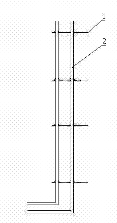
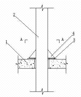
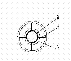
[0010] like figure 1 , 2 , 3, including floor 1, metal pipe 2, ring tray 3, supporting steel plate 4.
[0011] The above-mentioned metal pipes 2 vertically run through each floor 1 of a high-rise building, and an annular tray 3 is placed on each corresponding floor 1 floor. Distributed triangular supporting steel plates 4, each supporting steel plate 4 is welded and fixed to the side wall of the metal pipe 2.
Login to View More PUM
 Abstract
The invention relates to a slideable annular tray bracket mounting structure of a large-diameter stand pipe. The structure comprises a metal pipeline vertically penetrating through each floor of a high-rise building, and is characterized by also comprising multiple annular trays vertically arranged on the floorslab of each floor at intervals; the metal pipeline passes through the centers of the annular trays; multiple triangular support steel plates in radial distribution are uniformly distributed on the upper end surfaces of the annular trays; and the support steel plates are fixedly welded with the side wall of the metal pipeline. The annular trays are placed on the floorslab of each floor, the metal pipe is firmly welded with the triangular support steel plates, and the weight of the metal pipeline is transferred to the concrete floorslab through a tray bracket. Thus, the increased stress is not directly transferred to a basement horizontal U-steel bracket to cause damage. Since the trays are not fixed with the floor, the pipeline can freely extend upward for sure, and particularly after use, the metal pipeline with relatively great extension amount for storing and transporting cold / hot medium can be fixed in the floor.
Description
technical field [0001] The invention relates to a pipeline installation structure in a building, in particular to a slidable ring-shaped tray support installation structure for large-diameter standpipes. Background technique [0002] The engineering air-conditioning machine room of a high-rise building is located in the basement, the cooling tower is located on the roof, and the chilled water and cooling water standpipes are located in the pipeline well. The main riser of the air-conditioning water system uses a maximum of DN300 seamless steel pipe. It is generally difficult for the pipe support in the pipe well to be fixed and withstand such a large load. If it is considered that it is filled with medium (usually water) during operation, its own weight will double. The traditional solution is to firmly weld the standpipe and each layer of channel steel brackets in the tube well, and distribute the weight of the pipe itself to each layer of brackets evenly, instead of just ...
Claims
Login to View More Application Information
Patent Timeline
 IPC IPC(8): F16L5/00
Inventor江林宗山尧陈宇周永根
OwnerJIANGSU JIANGZHONG GROUP