Method for operating tail gas quality flow sensor

A technology of mass flow and sensors, applied in the direction of indirect mass flowmeters, mass flow measurement devices, etc., can solve the problems of distortion of measurement results, deposition, inaccurate determination of exhaust gas mass flow, etc., and achieve the effect of less loss

Inactive Publication Date: 2012-10-17
PIERBURG GMBH & CO KG NEUSS
View PDF1 Cites 0 Cited by
  • Summary
  • Abstract
  • Description
  • Claims
  • Application Information

AI Technical Summary

Problems solved by technology

[0003] The use of exhaust mass flow sensors in the exhaust mass flow of vehicles has so far only been realized to a limited extent
This is due on the one hand to the high temperatures that occur and on the other hand to the particles contained in the vehicle's exhaust gas causing deposits on the exhaust gas mass flow se

Method used


Image

  • Method for operating tail gas quality flow sensor

Examples


Embodiment Construction

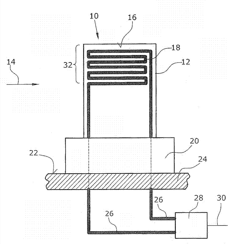
[0019] The exhaust gas mass flow sensor 10 has a substantially square carrier 12 . Said support body 12 , preferably of ceramic, has a width in the range of 2 to 10 mm, a height in the range of 2 to 20 mm, and a thickness in the range of 0.1 to 0.5 mm. In a preferred orientation of the exhaust gas mass flow sensor in the incoming flow, the thickness of the carrier is from the side where the exhaust gas flows. The narrow side of the support body 12 is inflowed by the exhaust gas mass flow in the direction of the arrow 14 . A heating element 18 is provided on the surface 16 of the carrier. The heating element 18 can also be arranged inside the carrier body 12 .

[0020] The carrier body 12 is arranged via a holding element 20 on an inner side 22 of an exhaust gas duct 24 .

[0021] The heating element 18 is connected to a control device 28 via a line 26 . The control device 28 can be connected with the on-board electronic devices and the like through wires 30 . Heating of t...


PUM


Abstract

The invention relates to a method for operating a tail gas quality flow sensor, and particularly relates to a method for operating a tail gas quality flow sensor in automobile tail gas quality flow. The tail gas quality flow sensor is operated in an operation mode and at an operation temperature and is converted into a purification mode for purifying a measuring area (32), wherein a purification temperature is higher than the operation temperature; the tail gas quality flow sensor is connected with a control device (28); the purification mode is activated through the control device (28) according to characteristic data; and moreover, the heating time of the tail gas quality flow sensor is taken as the characteristic data.

Description

technical field [0001] The present invention relates to a method of operating an exhaust gas mass flow sensor. In particular, the invention relates to a method for operating an exhaust gas mass flow sensor in the exhaust gas mass flow in a motor vehicle. Background technique [0002] The exhaust gas mass flow sensor has, for example, a cuboid carrier on which a heating element, for example in the form of a conductor track, is mounted. The support body is usually fixed in the exhaust gas channel by holding elements, so that the support body is infiltrated by the exhaust gas mass flow on its narrow side and the exhaust gas mass flow flows along the wide sides of the support body. In particular, heat transfer from the heating element to the exhaust gas mass flow is achieved by convection. By measuring the temperature change or measuring the power consumption required to keep the temperature of the heating element constant, the exhaust gas mass flow can be determined by means ...

Claims


Application Information

Patent Timeline
IPC IPC(8): G01F1/86
Inventor 卡尔-海因里希.洛辛格斯文.尼格林卡斯滕.格里姆海因里希.迪斯蒙安德烈亚斯.汤尼斯曼
Owner PIERBURG GMBH & CO KG NEUSS
Why Eureka
Try Eureka