
Large view field projection lithography objective lens

A technology of projected light and large field of view, applied in the field of optics, can solve the problems of increasing the overall volume of the optical system, and achieve the effect of increasing the field of view and controlling the difficulty of processing

Active Publication Date: 2012-10-17
SHANGHAI MICRO ELECTRONICS EQUIP (GRP) CO LTD
View PDF4 Cites 3 Cited by
  • Summary
  • Abstract
  • Description
  • Claims
  • Application Information

AI Technical Summary

Problems solved by technology

The second embodiment of the patent increases the field of view, which also depends on the increase in the aperture of the reflective primary mirror, and at the same time the overall volume of the optical system also increases

Method used


Image

  • Large view field projection lithography objective lens
  • Large view field projection lithography objective lens
  • Large view field projection lithography objective lens

Examples


Embodiment Construction

[0021] Specific embodiments of the present invention will be described in detail below in conjunction with the accompanying drawings.

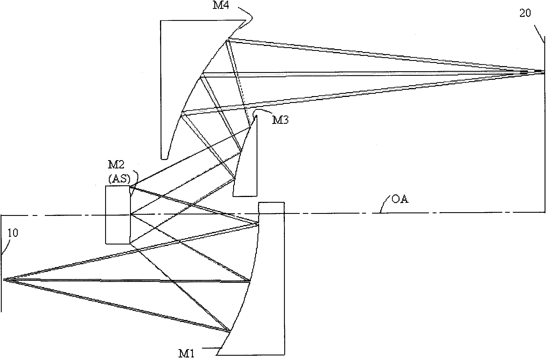
[0022] Such as figure 1 As shown, the projection lithography objective lens of the present invention is made up of 4 reflecting mirrors, and each parameter requirement is as shown in table 1

[0023] Table 1

[0024] Working wavelength

ghi line

Image side numerical aperture NA

0.11

Magnification

-2

Object distance

1500mm

[0025] Such as figure 1 As shown, the projection lithography objective lens of the present invention is a purely reflective design consisting of four mirrors. The first reflector M1 is a concave reflector; the second reflector M2 is a convex reflector; the third reflector M3 is a convex reflector; and the fourth reflector M4 is a concave reflector. All four mirrors are located on the same optical axis OA. The aperture stop AS is disposed close to the second mirro...


PUM

PropertyMeasurementUnit
Widthaaaaaaaaaa
Longitudinal lengthaaaaaaaaaa

Abstract

The invention provides a large view field projection lithography objective lens. The large view field projection lithography objective lens is characterized in that the large view field projection lithography objective lens is an optical system consisting of four reflecting mirrors whose curvatures are not zero, and the focal points of the four reflecting mirrors are located on the same optical axis. The four reflecting mirrors include two concave reflecting mirrors and two convex reflecting mirrors. The following relationships are satisfied in the four reflecting mirrors: the absolute value of a quotient of f1 divided by f2 is greater than 0.45 and less than 0.85, the absolute value of a quotient of f3 divided by f4 is greater than 0.35 and less than 0.80, and the absolute value of a quotient of f1 divided by f4 is greater than 0.40 and less than 0.70, wherein the f1, the f2, the f3, and the f4 are the focal lengths of the first reflecting mirror, the second reflecting mirror, the third reflecting mirror, and the fourth reflecting mirror respectively. According to the large view field projection lithography objective lens of the invention, the view field can be increased by changing positions and focal powers of the four reflecting mirrors instead of completely relaying on the diameters of the reflecting mirrors, so that the processing difficulty is effectively controlled.

Description

technical field [0001] The invention relates to the field of optical technology, in particular to a large field of view projection lithography objective lens of a semiconductor lithography device. Background technique [0002] At present, in the field of semiconductor or liquid crystal flat panel (FPDs) processing, catadioptric or total reflection systems have many different forms of applications due to their advantages in chromatic aberration correction. And most of them take large exposure field of view and wide spectral bandwidth as the main design goals. At the same time, in order to match the size of the mask, many optical systems use projection objectives with a magnification greater than 1 or even close to 2 times. [0003] US2004 / 0263429A1 discloses a projection objective lens for flat panel displays (FPDs), whose exposure spectrum is ghi lines, mainly composed of a reflective primary mirror (which can be divided into two parts) and a reflective secondary mirror. Th...

Claims


Application Information

Patent Timeline
IPC IPC(8): G02B17/06G02B5/10G02B13/06G02B13/22G02B13/26G03F7/20
Inventor 武珩黄玲郭银章
Owner SHANGHAI MICRO ELECTRONICS EQUIP (GRP) CO LTD
Learn More