Process and plant for cooling acid

A technology for cooling equipment and equipment, applied in lighting and heating equipment, mechanical equipment, sulfur compounds, etc., can solve problems such as damage to tube bundles, damage to pot boilers, etc.

Active Publication Date: 2014-11-19
METSO OUTOTEC (FINLAND) OY
View PDF7 Cites 0 Cited by
  • Summary
  • Abstract
  • Description
  • Claims
  • Application Information

AI Technical Summary

Problems solved by technology

Risk of damaging the tube bundle or even the entire kettle boiler
Furthermore, acid / water mixtures can only be separated with disproportionate effort, so that in practice the user will almost have to completely empty one or both systems

Method used


Image

  • Process and plant for cooling acid
  • Process and plant for cooling acid
  • Process and plant for cooling acid

Examples


Embodiment Construction

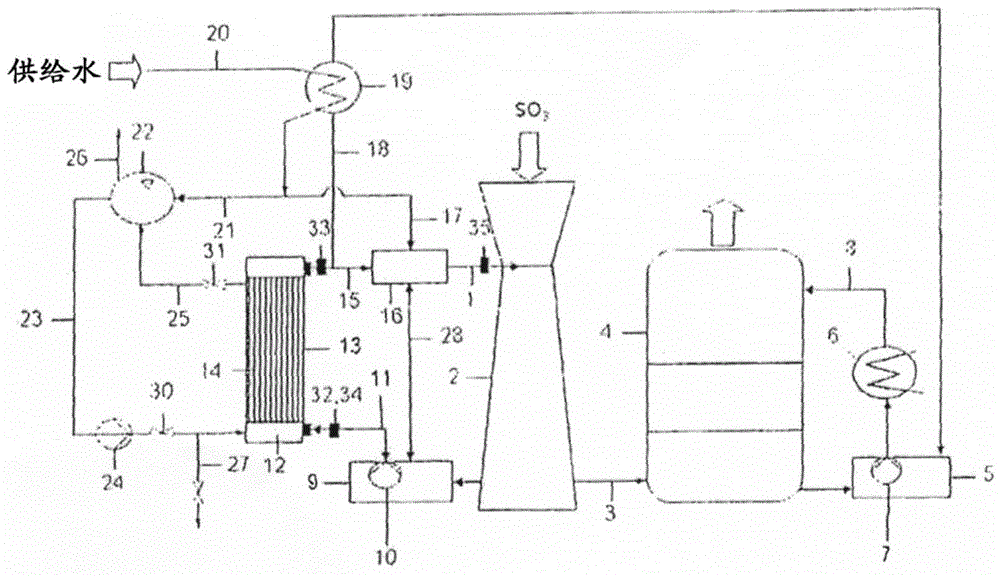
[0027] as from figure 1 The flow chart of the process of the present invention shown in can be seen from the SO 2 converted to SO 3 Gaseous sulfur trioxide from a converter not shown is introduced into the Venturi absorber 2 cocurrently with the concentrated sulfuric acid supplied through conduit 1 and is partially absorbed in the hot acid whose concentration is thereby increased . Via conduit 3, unabsorbed sulfur trioxide is introduced into intermediate absorber 4 where it is passed countercurrently through concentrated sulfuric acid for further absorption. Unabsorbed sulfur trioxide is withdrawn from the top of the intermediate absorber 4 and supplied to a catalytic conversion stage not shown, while enriched sulfuric acid is withdrawn at the bottom, partly removed as product or otherwise used in the plant, After dilution with water in acid pump tank 5 and cooling in heat exchanger 6 , the remaining enriched sulfuric acid is recycled by pump 7 via conduit 8 to intermediate...


PUM


Abstract

A process for cooling an acid that is withdrawn from an absorption apparatus of a sulfuric acid plant includes pumping the acid to be cooled from an acid pump tank and supplying the acid to a shell space of a heat exchanger. Water is supplied as a heat transport medium to heat transfer elements disposed in the shell space so as to at least partially convert, by heat transfer from the acid, the water to steam. The acid which was cooled in the heat exchanger is supplied back to the absorption apparatus. The water is separated from the steam in a steam drum. The separated water is recirculated to the heat exchanger using a pump.

Description

technical field [0001] The invention relates to the cooling of acid drawn from the absorption plant of a sulfuric acid plant, wherein the acid is pumped from the acid pump tank into a heat exchanger and subsequently supplied to said absorption plant, wherein water as heat transfer medium is heated The heat from the acid is heated in an exchanger and at least partially converted into steam, and the water is separated from the steam therein. Background technique [0002] Sulfuric acid is usually produced by the so-called double absorption process, as described in Ullmann's Encyclopedia of Industrial Chemistry, 5th Edition, Vol. A25, pp. 635 to 700. Sulfur dioxide (SO 2 ) is converted to sulfur trioxide (SO 3 ). Obtained SO 3 is withdrawn after the contacting stage of the converter and supplied to an intermediate absorber or after the last contacting stage of the converter to a final absorber in which SO is contained 3 The gas is directed countercurrently to the concentrat...

Claims


Application Information

Patent Timeline
Patent Type & Authority Patents(China)
IPC IPC(8): C01B17/765C01B17/80
CPCF01K17/06F28D7/16F28D9/00C01B17/7655C01B17/806F01K23/064B01J8/26
Inventor K-H·道姆W·沙尔克
Owner METSO OUTOTEC (FINLAND) OY
Why Eureka
Try Eureka