Ultrasonic atomization film spraying coater
A technology of ultrasonic atomization and ultrasonic atomizer, which is applied in coatings and devices for coating liquid on the surface, etc., can solve the problems of lack of standardized equipment and restrictions on popularization and application, and achieve a wide sales market, convenient manufacture, and simple structure Effect
- Summary
- Abstract
- Description
- Claims
- Application Information
AI Technical Summary
Problems solved by technology
Method used
Image

Examples
Embodiment Construction
[0039] Below in conjunction with accompanying drawing and embodiment the present invention will be further described:
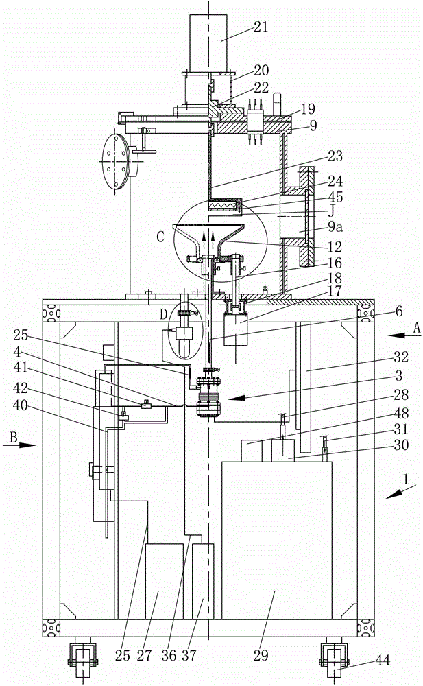
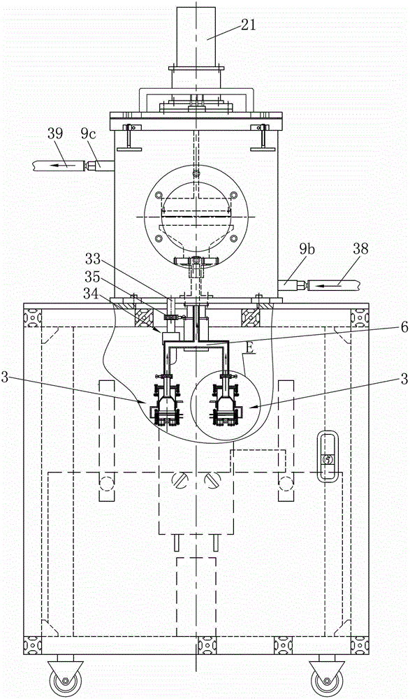
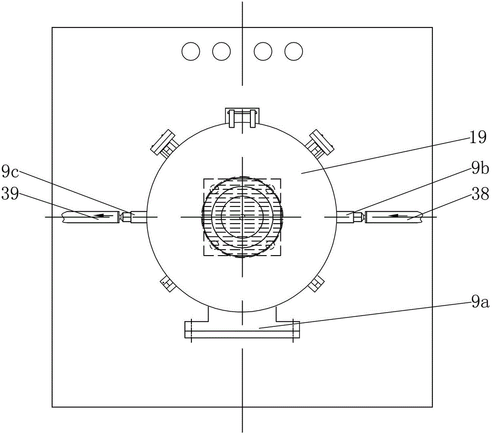
[0040] Such as Figures 1 to 9 As shown, the present invention mainly consists of a frame 1, a liquid storage tank 2, an ultrasonic atomizer 3, a delivery pipeline 4, a first quick-release flange 5, a collecting pipe 6, a flow guide tube 7, and a second quick-release flange 8 , reaction chamber 9, installation sleeve 10, bearing 11, spraying cover 12, large gear 13, connecting sleeve 14, pinion gear 15, vertical shaft 16, first motor 17, mounting seat 18, top cover 19, bracket 20, the first Two motor 21, magnetic fluid seal 22, vertical rod 23, iodine tungsten lamp 24, three-way pipe 25, glass float flowmeter 26, air compressor 27, three-way water inlet pipe 28, water tank 29, pump 30, three-way Return pipe 31, mounting plate 32, discharge pipe 33, gas-liquid separator 34, third quick release flange 35, air pipe 36, vacuum pump 37, reaction chamber inlet pip...
PUM
| Property | Measurement | Unit |
|---|---|---|
| Thickness | aaaaa | aaaaa |
Abstract
Description
Claims
Application Information