Clamp for quickly clamping and positioning cylindrical components

A positioning fixture, a cylindrical technology, applied in positioning devices, metal processing machinery parts, clamping, etc., can solve the problems of low reuse rate of positioning holes, waste of time for positioning holes, and waste, so as to prolong the working time of the machine and shorten the working time of the machine. The effect of processing cycle and reducing processing cost

Inactive Publication Date: 2012-10-24
OECHSLER PLASTIC PROD TAICANG
View PDF23 Cites 9 Cited by
  • Summary
  • Abstract
  • Description
  • Claims
  • Application Information

AI Technical Summary

Problems solved by technology

However, its disadvantage is that it is wasteful, such as the waste of materials and the waste of time for processing positioning holes; in addition, the reuse rate of the positioning holes i

Method used


Image

  • Clamp for quickly clamping and positioning cylindrical components
  • Clamp for quickly clamping and positioning cylindrical components
  • Clamp for quickly clamping and positioning cylindrical components

Examples


Example Embodiment

[0020] The present invention will be further described below in conjunction with the accompanying drawings.

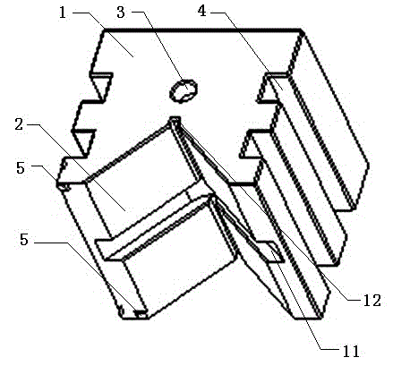
[0021] like figure 1 As shown, the front part of the main body 1 of the present invention is provided with a V-shaped positioning groove 2, the upper part is provided with a positioning hole 3, two positioning grooves 4 are respectively provided on both sides, and a group of verticality reference positioning blocks 5 are provided on the side of the main body 1 . In the V-shaped positioning groove 2, there is a workpiece hanging table avoidance groove 11. Since there are three constraints in the actual use and installation of general cylindrical parts, first, the coaxial constraint is on the outer peripheral surface; second, the axial direction Third, the rotation around the axis is constrained by the anti-rotation device. The escape groove 11 in the present invention is used to avoid the hanging platform with a thickness of 2-10mm, and can simultaneously clamp two ide...


PUM


Abstract

The invention discloses a clamp for quickly clamping and positioning cylindrical components. The clamp comprises a main body, wherein a V-shaped positioning groove is formed in the front of the main body; a positioning hole is formed on the upper part of the main body; a cantilever is movably connected with the main body; and a group of positioning sheets are positioned at the back of the main body. The clamp has the characteristics of high repeated positioning accuracy and repeated utilization ratio; and moreover, each machining procedure can be joined in a seamless mode, and each procedure form a flexible manufacturing unit, so that the working time of a machine which generates direct value is prolonged, the set time of the machine which does not generate the value is shortened, the machining cost is reduced, and the accurate machining requirement of a large quantity of cylindrical components can be met.

Description

technical field [0001] The invention relates to a fast clamping and positioning fixture for cylindrical parts, which is applied in the field of mechanical processing. Background technique [0002] At present, there are mainly two clamping methods for wire cutting when processing cylindrical workpieces. [0003] The first one is to clamp the cylindrical surface of the workpiece with flat pliers, and then use the electrical contact of the machine tool to position it. The disadvantage is that it takes a long time to clamp and level the workpiece, and the positioning accuracy is low. It is generally used to process workpieces with a position accuracy of 0.02mm. [0004] The second method is to find a piece of material that is much larger than the cylindrical workpiece to be processed, and process a hole on it with the same diameter as the workpiece to be processed. The tolerance is controlled at 0-0.005mm, and then the workpiece to be processed is Embedded in hole processing. ...

Claims


Application Information

Patent Timeline
IPC IPC(8): B23Q3/00B23H7/02B23H11/00
Inventor 姜卫星赖国皇倪雷
Owner OECHSLER PLASTIC PROD TAICANG
Why Eureka
Try Eureka