Industry and electricity integrated electric switch device with central locking polar integrated control unit

An electric and locking lever technology, which is applied to point switches, electrical equipment for manipulating turnouts or line breakers, and railway car body parts, etc. It can solve the problems of difficult electrical maintenance, low safety and reliability, and weak power, etc. problem, to achieve the effect of strong ability to adapt to ice and snow climate, simple and reliable transmission structure, and convenient polarity control

Inactive Publication Date: 2012-10-24
孙志伟
View PDF0 Cites 5 Cited by
  • Summary
  • Abstract
  • Description
  • Claims
  • Application Information

AI Technical Summary

Problems solved by technology

[0003] 1. The electric switch machine is installed on the external cantilever bracket, the system rigidity is low, the anti-interference ability is poor, the safety reliability is not high, the power is not strong, the assembly inspection and transportation cannot be carried out, and large-scale mechanized maintenance cannot be hindered;
[0004] 2. Although the single-hook external lock method is partially strengthened, the double-safety and double-lock functions are weak, and there are crawling jams, tilting and jumping of the heart rail, multi-point asynchronous interference, sand, dust, ice and snow damage and other unsafe and unreliable factors. Fork squeeze alarm function; large amount of maintenance, only used for high-speed roads, consumes residual synchronization technology, low efficiency; AC motor, small starting torque, power step-down, overload, easy to stall and burn, complex control and protection technology, electrical appliances , The amount of cable is large;
[0005] 3. Although the ZD6 type internal locking method has complete functions, the locking and squeezing functions of the switch machine are opposite to each other. The circular arc locking wears a lot and the efficiency is low; the load capacity of the planetary bearing of the reducer is insufficient, and the service life is low; the DC motor has a four-wire switch control circuit and the double excitation coil is seriously squeezed; Two hidden dangers of wire breakage: the linkage of the sharp rails, the curved and slender connecting rods, the low reliability of inspection and locking, and cannot be used for high-speed turnouts, the resistance to crushing is large, the squeezeability is poor, the range of crushing damage is large, and the alarm is not sensitive; The four point rails of the sub-turnout are linked, and the connecting rods are crossed and overlapped. There is a risk of loss of the point rails, and it is difficult to maintain the labor and electricity. The structure of the slow-moving electric switch machine cannot be used universally

Method used


Image

  • Industry and electricity integrated electric switch device with central locking polar integrated control unit
  • Industry and electricity integrated electric switch device with central locking polar integrated control unit
  • Industry and electricity integrated electric switch device with central locking polar integrated control unit

Examples


Embodiment Construction

[0044] specific implementation plan

[0045] 1. Central lock electric switch machine

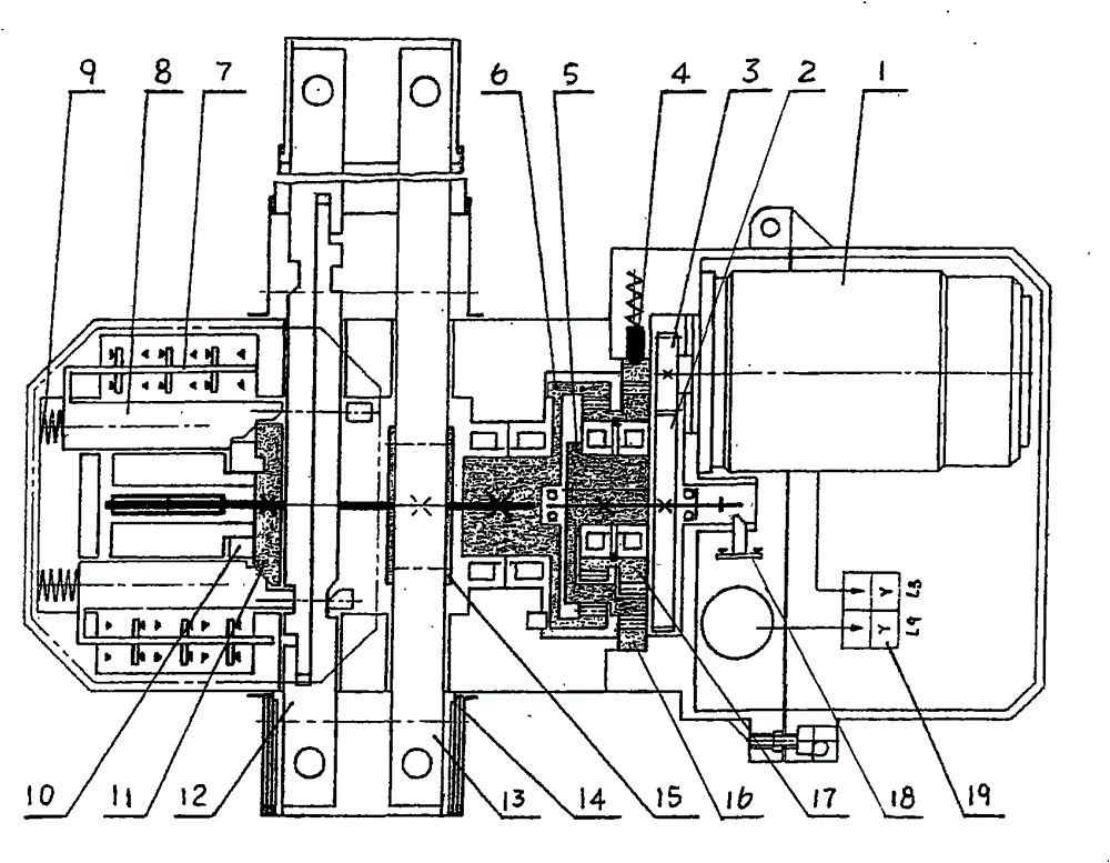
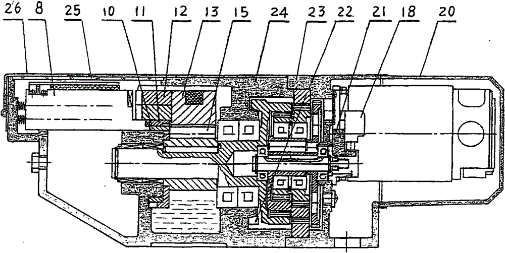
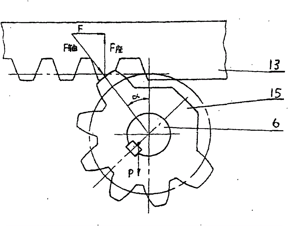
[0046] The working principle and structural axial section of the central lock electric switch machine 32, such as figure 1 , 2 As shown, it consists of power, deceleration, motion detection, and display four chambers connected in series. DC motor 1, through Z1 pinion 3 / band Z2 large gear input shaft 2 / 2K-H / band stopper Z6 output wheel shaft 6 / moving lock wheel 15 / moving lock bar 13, complete the left position moving lock (as image 3 shown). Simultaneously, start plate 11 pushes out left inspection lock block 8, and right inspection lock bar 12 unlocks, and the left indication switch 7 of linkage with left inspection lock block 8 disconnects right position indication, and right inspection lock block 8 is in two internal inspection lock springs 9 Under the promotion of the switch, insert the locking straight mouth of the left check lock lever 12 linked with the switch rail, the check obli...


PUM


Abstract

The invention relates to a railway industry and electricity integrated electric switch device with a central locking polar integrated control unit. A high-strength anti-retreating moving lock mechanism, an integrated visible lock checking expression mechanism, a closed oil immersion overload unloading double speed transmission mechanism, a double speed, rapid stopping and high-efficiency permanent magnet direct-current motor and the like are integrated to form a compact non-squeezable central locking electric switch machine, wherein the high-strength anti-retreating moving lock mechanism is composed of a ball iron box seat/a heavy-duty bearing/an upper rack moving lock rod/a short and thick tooth crest lock; a lock checking rod/a direct-acting contact expression switch/a four-head lock checking block/a spiral starting disk/an axial quick-acting ring which are flatly placed and connected by body separation form the integrated visible lock checking expression mechanism; the closed oil immersion overload unloading double speed transmission mechanism integrates a 2K-H displacement and variable level differential transmission shaft with multiple tooth differences and short teeth, a stopping output wheel shaft with an eccentric bushing hammer; the compact central locking electric switch machine which can not be squeezed, a lengthened rail brace slide plate ( base rail/ switch tie) central multi-lug insulation hinge, a crank and straight linked arm and a linked switch rail and point rail form an industry and electricity integrated squeezable and non-squeezable unit by means of a zero-clearance sleeved elasticity group pin and a double-port microgap hinge, low speed turnout unitization of single opening and single action, double slip separated action, hump double action and the like is achieved, a intermediate speed and high speed turnout switch rail and a point rail are synchronous in sections and combined with combination unitization to form the safe, reliable, advanced, adjustment-free, protection-free and industry and electricity assembled power-driven turnout of the whole transmission and whole spreading central locking electrode control device.

Description

technical field [0001] The electric switch equipment of the central lock pole control unit integrated with engineering and electricity is a new generation of electric switch equipment for railway turnouts. technical background [0002] The existing equipment has the following deficiencies: [0003] 1. The electric switch machine is installed on the external cantilever bracket, the system rigidity is low, the anti-interference ability is poor, the safety reliability is not high, the power is not strong, the assembly inspection and transportation cannot be carried out, and large-scale mechanized maintenance cannot be hindered; [0004] 2. Although the single-hook external lock method is partially strengthened, the double-safety and double-lock functions are weak, and there are crawling jams, tilting and jumping of the heart rail, multi-point asynchronous interference, sand, dust, ice and snow damage and other unsafe and unreliable factors. Fork squeeze alarm function; large a...

Claims


Application Information

Patent Timeline
Patent Type & Authority Applications(China)
IPC IPC(8): B61L5/06E01B7/14
Inventor 孙志伟
Owner 孙志伟
Why Eureka
Try Eureka