
Measurement method and device for optical voltage transformer dynamic property research

A technology of optical voltage and dynamic performance, which is applied in the direction of measuring devices, instruments, and measuring electrical variables, etc., can solve the problem of difficult real-time monitoring of the closed-loop state of the system, the difficulty of approaching the dynamic model of the real signal detection unit, and the unfavorable dynamics of optical voltage transformers. Performance and other issues

Active Publication Date: 2015-02-04
安徽华驰动能科技有限公司
View PDF3 Cites 0 Cited by
  • Summary
  • Abstract
  • Description
  • Claims
  • Application Information

AI Technical Summary

Problems solved by technology

In the prior art, the closed-loop control process of the optical voltage transformer system is carried out in the FPGA, and the closed-loop state variables change rapidly at the microsecond level, so it is difficult to monitor the closed-loop state of the system in real time
In the prior art, the model of the internal module of the optical voltage transformer system is often established through theoretical derivation, which is difficult to approach the dynamic model of the real signal detection unit, which is not conducive to the development of the research work on the dynamic performance of the optical voltage transformer

Method used


Image

  • Measurement method and device for optical voltage transformer dynamic property research
  • Measurement method and device for optical voltage transformer dynamic property research
  • Measurement method and device for optical voltage transformer dynamic property research

Examples


Embodiment Construction

[0022] The present invention will be described in detail below in conjunction with the accompanying drawings and embodiments.

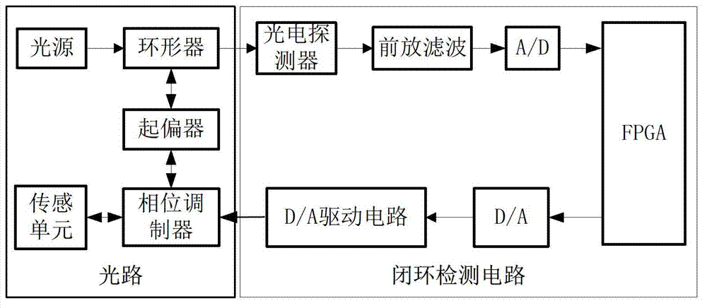
[0023] Such as figure 1 Shown is a schematic diagram of the principle structure of an optical voltage transformer based on the Pockels effect in the prior art, which is composed of an optical circuit and a closed-loop detection circuit. The optical path part includes light source, circulator, polarizer, phase modulator and sensing unit, and the closed-loop detection circuit includes photodetector, preamp filter circuit, A / D converter, FPGA, D / A converter and D / A Drive circuit. The light emitted by the light source passes through the circulator, the polarizer, and the phase modulator in sequence, and then reaches the sensing unit. Due to the Pockels effect, the sensing unit converts the voltage signal to be measured to carry a non-mutual phase difference The optical signal returns to the phase modulator and the polarizer through the action of the r...


PUM


Abstract

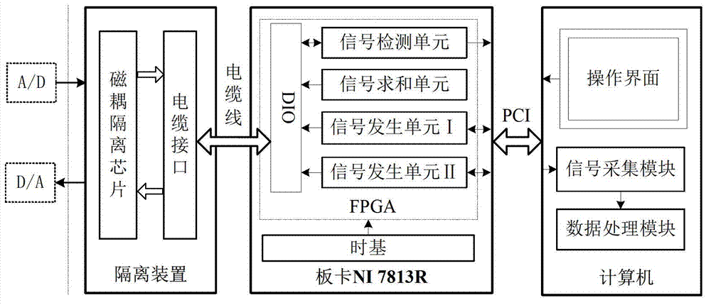
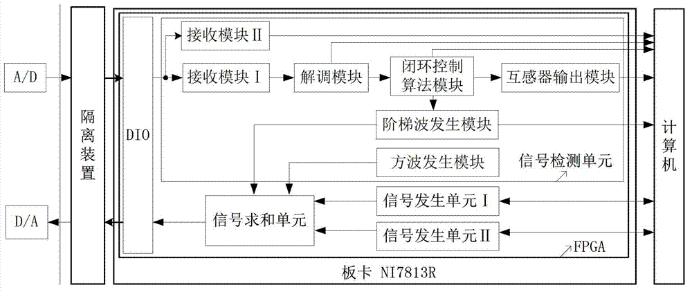
The invention discloses a test method and a device for optical voltage transformer dynamic property research. A board NI7813R which contains field programmable gate array (FPGA) is utilized to substitute the FPGA in the closed-loop detection circuit of the original optical voltage transformer, an isolation device is arranged between an analog-digital / digital-analog converter of the closed-loop detection circuit and the FPGA of the board NI7813R for connection and communication, and the FPGA of the board NI7813R is connected with a computer through a peripheral component interconnect (PCI) bus; the test device has the capabilities of high speed data acquiring, storing and processing, closed-loop state variables can be displayed and stored by the computer, so the working condition of a system closed loop is monitored in real time; no other external equipment is needed, sine excitation signals and step-input singles with tunable frequency are provided by a hardware of the measurement device, so the frequency characteristic and the closed-loop step response performance of an optical voltage mutual inductance system are tested; and the frequency characteristic of an internal function module in an optical voltage transformer can be tested, a high frequency dynamic model of the module is built, and a foundation is laid for the optical voltage transformer dynamic property research.

Description

technical field [0001] The invention relates to an optical voltage transformer, in particular to a testing method and device for researching the dynamic performance of an optical voltage transformer based on the Pockels effect. Background technique [0002] Dynamic performance research is an important part of optical voltage transformer research. The national standard IEC 60044-8 has made clear requirements for the dynamic performance of optical voltage transformers: in high voltage measurement, voltage transformers should have at least a frequency response of several KHz characteristics and a response time of a few milliseconds, for some applications such as traveling wave protection relays, measurement frequencies up to hundreds of kHz are required. According to the existing literature, the existing domestic and foreign optical voltage transformers based on the Pockels effect have a maximum bandwidth of 40kHz, and the existing domestic and foreign optical voltage transform...

Claims


Application Information

Patent Timeline
Patent Type & Authority Patents(China)
IPC IPC(8): G01R35/02
Inventor 李慧毕兰崔利阳李立京许文渊张春熹
Owner 安徽华驰动能科技有限公司
Learn More