
Multiwave beam-based depth-sounding joint inversion method for sound velocity profile and seafloor topography

A technology of sound velocity profile and joint inversion, applied in the direction of sound wave reradiation, measurement of propagation velocity, radio wave measurement system, etc., can solve the problems affecting the working efficiency and long time of multi-beam sounding system

Inactive Publication Date: 2012-10-24
北京南界电子技术有限公司 +1
View PDF6 Cites 42 Cited by
  • Summary
  • Abstract
  • Description
  • Claims
  • Application Information

AI Technical Summary

Problems solved by technology

Using the method of point-by-point measurement to obtain the sound velocity profile often requires the mother ship to be moored for measurement, which requires a lot of manpower and material resources
However, the actual marine environmental conditions are complex and changeable. Factors such as the inflow of fresh water at the estuary of the river, the movement of water masses, and the temperature difference between day and night all cause the seawater sound velocity profile to change with time and space. It takes a long time to obtain the sound velocity profile of a large sea area, which directly affects the working efficiency of the multi-beam sounding system

Method used


Image

  • Multiwave beam-based depth-sounding joint inversion method for sound velocity profile and seafloor topography
  • Multiwave beam-based depth-sounding joint inversion method for sound velocity profile and seafloor topography
  • Multiwave beam-based depth-sounding joint inversion method for sound velocity profile and seafloor topography

Examples


Embodiment Construction

[0043] Below in conjunction with accompanying drawing and embodiment the present invention will be described in further detail:

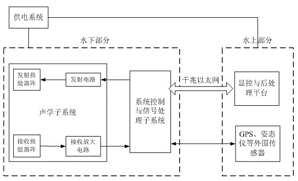
[0044] Such as figure 1 As shown, the current multi-beam sounding system usually includes:

[0045] - Transmitting circuit: used to transmit electrical signals.

[0046] ——Transmitting transducer array: used to convert the transmitted electrical signal into an acoustic signal, and transmit the acoustic signal to the measurement sea area.

[0047] ——Receiving transducer array: used to receive the echo of the acoustic signal emitted by the transmitting transducer array, and convert the echo acoustic signal into an electrical signal.

[0048] ——Receiving amplifying circuit: used to amplify the electrical signal converted by the receiving transducer array.

[0049] ——System control and signal processing subsystem: used to realize high-speed signal acquisition and real-time processing, and transmit the collected data and processing results to the disp...


PUM


Abstract

The invention discloses a multiwave beam-based depth-sounding joint inversion method for a sound velocity profile and a submarine topography. The method comprises the following steps of: (1) transmitting multiwave beams to the seafloor of a sounded sea area through a transmitting transducer array of a multiwave-beam depth sounding system, and receiving echo signals through a receiving transducer array of the multiwave-beam depth sounding system; (2) obtaining the arrival angle and the arrival time of echoes according to the received echo signals by using the multiwave-beam depth sounding system; (3) establishing a state space model formed by using a state equation and a sounding equation; (4) obtaining inversion values of the sound velocity gradient and the seafloor depth of the sounded sea area by using a sequential filter method according to the established state space model and the arrival angle and the arrival time of received echoes, and obtaining an estimate of the sound velocity profile of the sounded sea area by using the inversion value of the sound velocity gradient; and further, calculating the water temperature profile of the sounded sea area by using the estimate of the sound velocity profile. According to the multiwave beam-based depth-sounding joint inversion method for the sound velocity profile and the submarine topography, disclosed by the invention, the estimates of the sound velocity profile and the depth of the seafloor can be obtained quickly and accurately.

Description

technical field [0001] The invention relates to the technical field of underwater acoustic measurement, in particular to a joint inversion method of sound velocity profile and seabed topography based on multi-beam bathymetry. Background technique [0002] Seabed topographic survey is an important means for human beings to explore oceans, develop ocean resources, design ocean engineering, and construct a virtual environment for ocean battlefields. For a long time, although the traditional single-beam echo sounding technology has played an important role in the survey of seabed topography, due to the defects of long measurement time, high cost, low precision and less information, it has been unable to meet the requirements of marine economic development, marine Contests of interest and the growing demands of marine planning and management. The multi-beam bathymetry technology has gradually become a very important and popular oceanographic measurement method due to its advanta...

Claims


Application Information

Patent Timeline
IPC IPC(8): G01S15/88G01H5/00
Inventor 张美佳章惠全徐文
Owner 北京南界电子技术有限公司
Learn More