
Regional loop controller in intelligent road lighting system

A lighting system and intelligent road technology, applied in the direction of energy-saving lighting, energy-saving control technology, lighting devices, etc., can solve the problem of increasing the unsafe factors of the lighting system, and achieve the effect of reducing energy consumption and efficient lighting

Inactive Publication Date: 2012-10-24
TONGJI UNIV
View PDF6 Cites 5 Cited by
  • Summary
  • Abstract
  • Description
  • Claims
  • Application Information

AI Technical Summary

Problems solved by technology

Publication No. CN201230391Y patent "LED street lamp control device by time period", divides 24 hours a day into several time periods, different time periods generate pulses of different widths, and the pulse control drive circuit lights up the LED lights. The advantage lies in the introduction of multi-level control of the brightness of LED street lights And the concept of time division, the disadvantage is the lack of flexible control of the real-time data of the road section
Publication No. CN102307414A patent "Intelligent Street Light System Based on Measuring Traffic Flow" proposes an intelligent street light system for measuring traffic flow, which realizes the function of turning on when there is a car and turning off when there is no car in road lighting. The advantage of this patent is that it has a vehicle sensing effect , the disadvantage is that it can only adjust the two states of street lights on and off, and the street lights can only be turned on when the car travels to this node, which increases the unsafe factors of the lighting system

Method used


Image

  • Regional loop controller in intelligent road lighting system
  • Regional loop controller in intelligent road lighting system
  • Regional loop controller in intelligent road lighting system

Examples


Embodiment 1

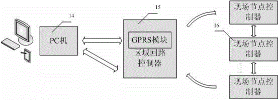
[0032] Embodiment 1: as figure 1 As shown, the regional loop controller 15 of the present invention, the PC 14 and the field node controller 16 constitute a perception-based intelligent road lighting energy-saving control system. The communication between the monitoring center of the PC 14 and the regional loop controller 15 can adopt a wired RS232 bus, or a wireless GSM / GPRS, and a self-defined protocol is adopted between the PC 14 and the regional loop controller. The regional loop controller 15 communicates with a plurality of field node controllers 16 through RS485 bus, and the communication protocol complies with the MODBUS communication protocol.

[0033] The MODBUS communication between the regional loop controller 15 and the field control nodes is initiated by the regional loop controller, and is divided into two types: MODBUS query and adjustment.

[0034] The MODBUS query frame format of the regional loop controller consists of access node number, function code, sta...


PUM


Abstract

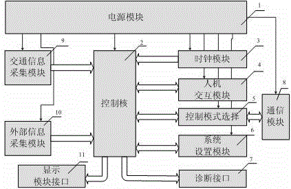
The invention provides a regional loop controller in an intelligent road lighting system. The regional loop controller, a PC (personal computer) machine and a scene node controller form a road lighting control system which can sense external environment change and a lighting system service body in real time, and can provide high lighting quality in remote. The regional loop controller is connected with the PC machine and the scene node controller, and is the pivot of the intelligent lighting control system; and the regional loop controller and the scene node controller form a master-slaver structure, and analyze and realize control strategy and management information query of the PC machine. As shown in the figure, the regional loop controller comprises a power supply module, a control core, a clock module, a human-computer interaction module, a control module selecting module, a system setting module, a diagnose interface, a communication module, a traffic information acquisition module, an external information acquisition module and a display module interface. The regional loop controller, the scene node controller and the PC machine form an integrated novel application system which is high-efficient in lighting, intelligent in control, energy saving and consumption-reduction, and lights according to needs.

Description

technical field [0001] The invention relates to an area loop controller in an intelligent road lighting system. Background technique [0002] In the field of road lighting, in terms of control strategy, the road lighting management systems of most cities in China are still using simple timing control methods. These systems generally have limitations such as difficulty in feeding back street lamp operating status information and remote control, and basically have no power-saving effect. [0003] The existing road lighting loop controller has few input and output channels and poor human-computer interaction function. Publication No. CN201230391Y patent "LED street lamp control device by time period", divides 24 hours a day into several time periods, different time periods generate pulses of different widths, and the pulse control drive circuit lights up the LED lights. The advantage lies in the introduction of multi-level control of the brightness of LED street lights And ...

Claims


Application Information

Patent Timeline
Patent Type & Authority Applications(China)
IPC IPC(8): H05B37/02
CPCY02B20/48Y02B20/42Y02B20/40Y02B20/72
Inventor 许维胜余有灵张志明王翠霞
Owner TONGJI UNIV
Learn More