Well control and wellhead equipment pressure testing device

A kind of equipment and pressure testing technology, which is applied in the direction of wellbore/well components, earthwork drilling, construction, etc., can solve the problems of increased production cost, influence on pressure maintenance and stability, and complicated flow path, so as to reduce processing and pressure starting Fast, less leaky effect

Active Publication Date: 2015-04-29
QINGDAO ZHONGRUITAI MESNAC TECH CO LTD
View PDF6 Cites 0 Cited by
  • Summary
  • Abstract
  • Description
  • Claims
  • Application Information

AI Technical Summary

Problems solved by technology

[0003] The present invention solves the problem that the existing well control and wellhead equipment pressure test devices use two independent hydraulic medium injection ports and two channels, resulting in complex flow paths in the well control and wellhead equipment pressure test devices, increased production costs, and medium leakage points The probability increases, which will affect the technical problem of maintaining and stabilizing pressure for a long time. A combination of pressure test blind plate and well control and wellhead equipment flange is provided, and the same hydraulic medium injection port and wellhead equipment are used for pressure test of well control and wellhead equipment. The well control and wellhead equipment pressure test device of the channel simplifies the internal flow path of the pressure test device, reduces the production cost, reduces the probability of leakage points, and increases the reliability of long-term pressure maintenance and pressure stabilization

Method used


Image

  • Well control and wellhead equipment pressure testing device

Examples


Embodiment Construction

[0014] Description with reference to the accompanying drawings.

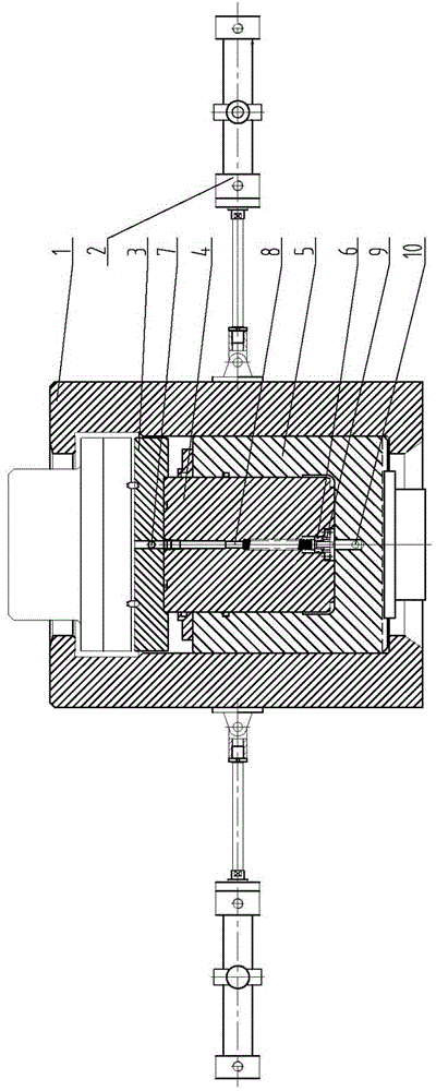
[0015] The high-pressure cylinder barrel 5 and the plunger 4 of the embodiment in the figure form a sealed cylinder. The high-pressure cylinder 5 is a fixed part of the sealed cylinder, which is fixedly installed on the base of the device; the plunger 4 is a moving part of the sealed cylinder. The blind flange 3 is detachably sealed and connected to the upper end surface of the plunger 4. Once the sealing groove on the blind flange 3 is damaged, only the blind flange 3 can be replaced to reduce the maintenance cost. The sealing groove on the upper end surface of the blind flange corresponds to the sealing groove on the bottom surface of the well control and wellhead equipment flange, and the sealing ring in the sealing groove seals and combines the blind flange 3 with the well control and wellhead equipment. The left and right half-open clamps 1 of the present embodiment are respectively hinged with a cylinder ...


PUM


Abstract

The invention discloses a well control and wellhead equipment pressure testing device which belongs to a pressure bearing safety performance testing device for well control and wellhead equipment and is used for testing the pressure bearing tightness of well control and wellhead equipment. A liquid injection channel at the center of a moving part of a sealing cylinder is connected with a center through hole of a blind flange and communicated into a cavity of well control and wellhead equipment, the liquid injection channel is provided with a back pressure valve, an inlet of the back pressure valve is communicated with a liquid injection hole, an outlet of the back pressure valve is communicated with the liquid injection channel, and the liquid injection hole is communicated with a medium pressure source. The well control and wellhead equipment pressure testing device solves the technical problems that a pressure testing blind plate of a conventional well control and wellhead equipment pressure testing device is combined with a flange plate of well control equipment, and two independent hydraulic medium injection ports and channels are used for pressure testing, so that the well control and wellhead equipment pressure testing device is complicated in flow path, and higher in manufacturing cost and medium leakage point probability, and long-time pressure maintaining and stabilizing are influenced. The well control and wellhead equipment pressure testing device has the advantages of fast pressure starting, few leakage points, reliable pressure stabilization, and low machining and manufacturing costs.

Description

technical field [0001] The invention belongs to a pressure-bearing safety performance detection device for well control and well head equipment, in particular to a pressure test device for well control and well head equipment. Background technique [0002] Well control in oil fields is related to production safety. The sealing and pressurization of well control and wellhead equipment pressure testing devices such as blowout preventers and Christmas trees are divided into two independent fluid flow systems. "Petroleum Machinery" in 2010, Volume 38, Issue 10, published the article "Research and Application of BOP Indoor and Field Pressure Test Process", which described the developed BOP pressure test connector, the BOP pressure test connector The piston seat is fixed, the hydraulic oil is injected into the piston seat, the top cylinder rises, and the clamp is hydraulically applied to make the flange of the BOP and the pressure test blind plate tightly combined; the high pressu...

Claims


Application Information

Patent Timeline
Patent Type & Authority Patents(China)
IPC IPC(8): E21B47/117E21B33/03
Inventor 刘建王中华苑香艳
Owner QINGDAO ZHONGRUITAI MESNAC TECH CO LTD
Why Eureka
Try Eureka