Smoke waste heat utilization system

A flue gas waste heat and heat recovery system technology, which is applied in the field of energy saving and emission reduction, can solve the problems that it is difficult to improve the efficiency of the heat recovery system, and achieve the effects of improving utilization, reducing emissions, and reducing heat consumption

Active Publication Date: 2012-10-31
XI AN JIAOTONG UNIV
View PDF8 Cites 33 Cited by
  • Summary
  • Abstract
  • Description
  • Claims
  • Application Information

AI Technical Summary

Problems solved by technology

However, for power plants in operation, it is difficult to improve the efficiency of the recuperation system by increasing the steam parameters. It is the only feasible way to o

Method used


Image

  • Smoke waste heat utilization system

Examples


Embodiment Construction

[0014] The present invention will be described in further detail below in conjunction with the accompanying drawings.

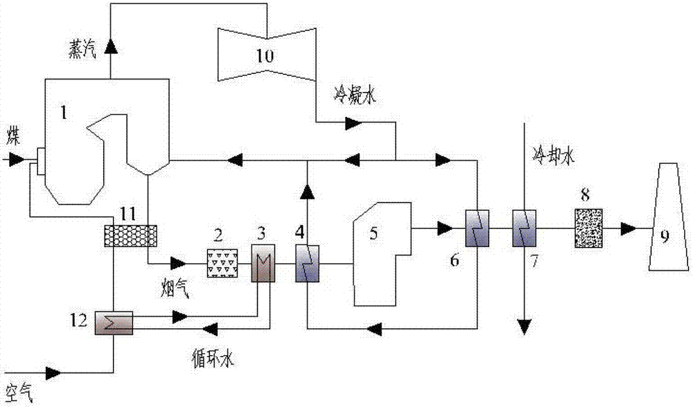
[0015] see figure 1 , the present invention includes a boiler 1 and an air preheater 11, an electric precipitator 2, a desulfurization tower 5, a carbon dioxide trap 8 and a chimney 9 that are connected to the flue gas outlet of the boiler 1 through a flue gas channel. An air heater 12 and an air preheater 11 are arranged in sequence on the inlet pipeline, and the first and second flue gas coolers 3 and 4 are installed between the electrostatic precipitator 2 and the desulfurization tower 5. The first flue gas cooler 3 The heat exchange tube and the air heater 12 form a closed circulation pipeline, and two condensing heat exchangers, namely the first and second condensing heat exchangers 6 and 7, are arranged between the desulfurization tower 5 and the carbon dioxide trap 8 , the cooling water is heated by the second condensing heat exchanger 7 for municipal...


PUM


Abstract

The invention discloses a smoke waste heat utilization system, wherein two condensation heat exchangers are added between a desulfurizing tower and a CO2 catching system, so as to absorb smoke heat and lower exhaust smoke temperature; and the absorbed heat is used for condensation water heating and municipal heating respectively. Two smoke coolers are arranged between an electric precipitator and the desulfurizing tower, and the heat recovered from the smoke is used for boiler primary air heating and further condensation water heating respectively. An air heater is arranged between an air inlet and an air preheater, and the heat recovered from the smoke by the smoke coolers is used for boiler primary air heating. The smoke waste heat utilization system can facilitate energy conservation and efficiency improvement for a power plant, and is particularly important for a running power plant which is difficult to improve the back-heating efficiency through increasing a steam parameter. Through optimizing running parameters of a unit, increasing condensation water heating bypasses and raising the temperature of the boiler primary air entering the air preheater, the heat consumption of a whole heating device can be lowered, the pollutant emission is reduced, and the energy utilization is improved.

Description

technical field [0001] The invention belongs to the field of energy saving and emission reduction, and in particular relates to a flue gas waste heat utilization system. Background technique [0002] my country's energy reserves are insufficient, but the demand is very strong. With the rapid economic development, China has now become the second largest energy consumption country in the world. The continuous increase of energy consumption has brought many social and environmental problems, and energy saving and consumption reduction have become imperative. Coal is the most important primary energy in my country, and coal-fired power generation plays a major role in power production. Improving power generation efficiency and reducing energy consumption are of great significance to energy conservation and emission reduction. Flue gas waste heat loss is the most important item in boiler heat loss, accounting for (4~8)% of the input heat of large and medium-sized boilers, and ab...

Claims


Application Information

Patent Timeline
IPC IPC(8): F22D1/36F23L15/00F23J15/00
CPCY02E20/34
Inventor 谭厚章杜文智刘原一张利孟
Owner XI AN JIAOTONG UNIV
Why Eureka
Try Eureka