Capacitive micro-electromechanical system (MEMS) accelerometer and manufacturing method thereof

An accelerometer, capacitive technology, applied in the measurement of acceleration, speed/acceleration/impact measurement, measurement devices, etc., can solve the problems of reduced yield and reliability, poor flexibility, and difficulty in repairing, to improve the yield, High reliability, flexible design effect

Active Publication Date: 2012-10-31
BEIJING MXTRONICS CORP +1
View PDF3 Cites 22 Cited by
  • Summary
  • Abstract
  • Description
  • Claims
  • Application Information

AI Technical Summary

Problems solved by technology

The comb-tooth accelerometer mainly has the following problems: the mechanical strength difference between the sensitive axis and the non-sensitive axis of the sensitive structure is not large, and the sensitivity of the non-sensitive axis of the accelerometer is difficult to suppress; the direction of the sensitive axis cannot provide a protective structure with sufficient mechanical strength , the impact resistance of the accelerometer is insufficient; the output value of the comb-tooth structure capacitance is small, and the sensitivity to external acceleration is low, so the comb-tooth accelerometer is mainly suitable for low-demand environments such as the consumer field
The traditional wire bonding technology is used for packaging. When the through hole of the accelerometer used to lead out the electrodes exceeds a certain depth, the difficulty of the wire bonding process will increase, and the yield and reliability will be significantly reduced; the repair is difficult and the flexibility is poor.

Method used


Image

  • Capacitive micro-electromechanical system (MEMS) accelerometer and manufacturing method thereof
  • Capacitive micro-electromechanical system (MEMS) accelerometer and manufacturing method thereof
  • Capacitive micro-electromechanical system (MEMS) accelerometer and manufacturing method thereof

Examples


Embodiment Construction

[0035] According to the working principle of capacitance detection, the MEMS accelerometer with all-silicon structure adopts a three-layer silicon structure: the metal electrode of the first silicon cover plate and the upper surface of the mass block of the middle silicon layer form the first capacitance, and the metal electrode of the second silicon cover plate and the mass of the middle silicon layer The lower surface of the block forms a second capacitor; under the action of acceleration perpendicular to the direction of the mass block, the mass block will shift, causing changes in the upper and lower capacitances. Acceleration can be measured by detecting changes in capacitance.

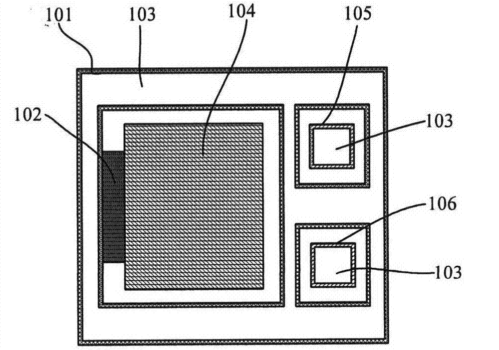
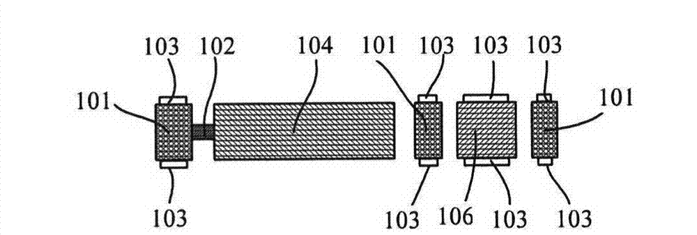
[0036]FIG. 1 is a schematic structural diagram of a silicon structure layer 1 , which includes a silicon frame 101 , a proof mass 104 , a support beam 102 , and silicon islands 105 and 106 . The mass block 104 is formed inside the silicon frame 101 , one end of the mass block 104 is connected to ...


PUM

PropertyMeasurementUnit
electrical resistivityaaaaaaaaaa

Abstract

The invention provides a capacitive micro-electromechanical system (MEMS) accelerometer, which comprises a first silicon cover plate layer, a middle silicon layer and a second silicon cover plate layer which are arranged in sequence, wherein the middle silicon layer comprises a first silicon island and a second silicon island; the silicon islands are formed inside a silicon framework and separated from the silicon framework at intervals; the first silicon island is contacted with a metal electrode of the first silicon cover plate layer; the second silicon island is contacted with a metal electrode of the second silicon cover plate layer; the first silicon cover plate layer further comprises a first metal electrode through hole, a second metal electrode through hole and a silicon electrode through hole which are formed in a first silicon substrate; the first metal electrode through hole corresponds to the position of the first silicon island; the second metal electrode through hole corresponds to the position of the second silicon island; the silicon electrode through hole corresponds to the position of the silicon framework; and an insulating layer is arranged on the inner wall of each through hole, and each through hole is filled with metal electrically conductive material. By adopting the capacitive MEMS accelerometer, all electrodes of the accelerometer can be led out on the same silicon surface, so that wafer level bonding of the accelerometer is realized and the accelerometer can be packaged by adopting the flip chip technology.

Description

technical field [0001] The invention relates to a microelectromechanical system (MEMS) device and its manufacturing technology, in particular to a capacitive MEMS accelerometer and its manufacturing method. Background technique [0002] MEMS accelerometers are an indispensable link in MEMS inertial systems and are currently used in many fields. There are two main working principles of MEMS accelerometers: capacitive and piezoresistive. Among them, piezoresistive accelerometers have disadvantages such as low precision and poor temperature characteristics, and their application fields are limited. Capacitive accelerometers mainly adopt two schemes: comb tooth type and "sandwich" type. The comb-tooth accelerometer mainly has the following problems: the mechanical strength difference between the sensitive axis and the non-sensitive axis of the sensitive structure is not large, and the sensitivity of the non-sensitive axis of the accelerometer is difficult to suppress; the direc...

Claims


Application Information

Patent Timeline
Patent Type & Authority Applications(China)
IPC IPC(8): G01P15/125
Inventor 杨静张富强孟美玉
Owner BEIJING MXTRONICS CORP
Why Eureka
Try Eureka