Omnidirectional radiation vibrator array antenna for loaded coupled feeding

A technology of omnidirectional radiation and coupling feeding, which is applied in the direction of antenna, antenna array, radiating element structure, etc., can solve the problems of poor omnidirectionality, low gain per unit electrical length, narrow bandwidth of omnidirectional antenna, etc., and achieve improvement of out-of-roundness High degree, conducive to miniaturization and mass production, and improve the omnidirectional effect

Active Publication Date: 2012-10-31
HARBIN INST OF TECH
View PDF4 Cites 5 Cited by
  • Summary
  • Abstract
  • Description
  • Claims
  • Application Information

AI Technical Summary

Problems solved by technology

[0004] The purpose of the present invention is to solve the problems of narrow bandwidth, low gain per unit electrical length, and poor omnidirectionality of existing omnidirectional antennas, and provide a loaded coupling-feed omnidirectional radiating oscillator array antenna

Method used


Image

  • Omnidirectional radiation vibrator array antenna for loaded coupled feeding
  • Omnidirectional radiation vibrator array antenna for loaded coupled feeding
  • Omnidirectional radiation vibrator array antenna for loaded coupled feeding

Examples


specific Embodiment approach 1

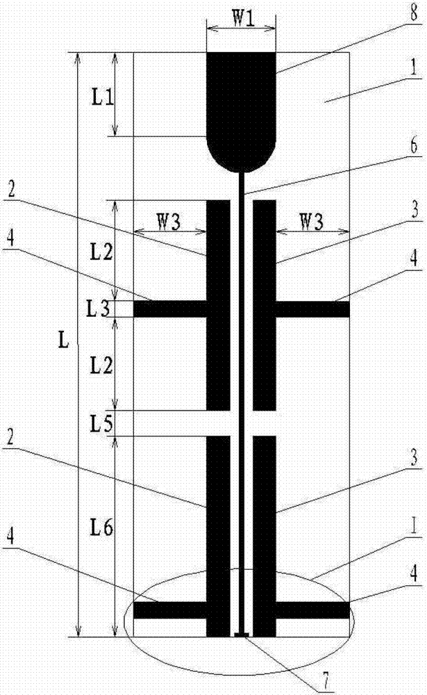
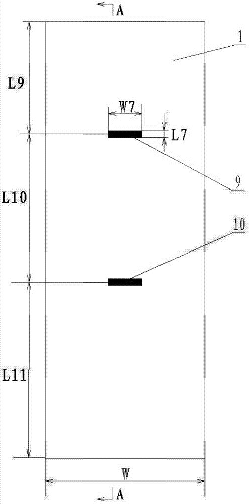
[0009] Specific implementation mode 1. Combination Figure 1 to Figure 5 This embodiment is described. The omnidirectional radiating dipole array antenna of the loading type coupling feeding in this embodiment includes a dielectric plate 1, a coplanar waveguide central feeder 6, a feeding port matching stub 7, a radial terminal load 8, and an upper horizontal feeder 9 , the lower horizontal feeder 10 and two groups of oscillators, the front of the dielectric board 1 is printed with two groups of oscillators, the coplanar waveguide center feeder 6, the feeding port matching branch 7 and the radial terminal load 8, the radial terminal load 8, the coplanar waveguide The central feeder 6 and the feeding port matching stub 7 are arranged sequentially from top to bottom, and the upper end of the coplanar waveguide central feeder 6 is connected to the radial terminal load 8, and the lower end of the coplanar waveguide central feeder 6 is connected to the feeding port matching stub 7 ...

specific Embodiment approach 2

[0010] Specific embodiment two, combine figure 1 The present embodiment will be described. The shape of the radial terminal load 8 of this embodiment is composed of a rectangle at the top and a semicircle at the bottom, and the short side of the rectangle is equal to the diameter of the semicircle. The length of the long side of the rectangle is L1, and the width of the short side (diameter of the semicircle) is W1. This design can play the role of radiating electromagnetic waves, thereby further improving the gain of the antenna. Other components and connections are the same as those in the first embodiment.

specific Embodiment approach 3

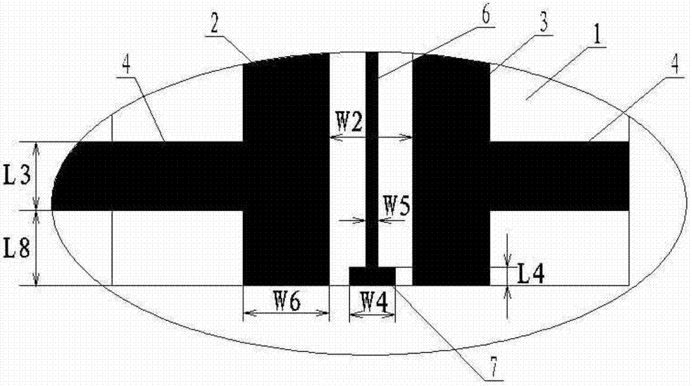
[0011] Specific embodiment three, combine figure 2 Describe this embodiment, the distance between the feeding port matching stub 7 and the left oscillator 2 and the distance between the feeding port matching stub 7 and the right oscillator 3 in this embodiment are equal. Other compositions and connections are the same as those in Embodiment 1 or 2.

[0012] The whole antenna is a double-sided printed circuit board, the thickness D1 of the dielectric board 1 is 1.5mm, and the dielectric constant ε of the dielectric board 1 is r It is a 4.4 epoxy (FR4) substrate.

[0013] The feed port is loaded with a feed port matching stub 7 to match the antenna feed, and the feed port matching stub 7 plays the role of adjusting the input impedance, making the feeding efficiency higher; loading a horizontal metal strip 4 is used to improve the antenna's The current distribution on the antenna makes the radiation current on the antenna more uniform, thereby greatly improving the out-of-roun...


PUM


Abstract

The invention discloses an omnidirectional radiation vibrator array antenna for loaded coupled feeding, which relates to an omnidirectional radiation vibrator array antenna and is used for solving the problems of small bandwidth, low unit electrical length gain and poor omni-directivity existing in the conventional omnidirectional antenna. The front face of a medium plate 1 is printed with two groups of vibrators, a coplanar waveguide central feeder line, a feeding port matching branch knot and radiation terminal load; the upper end of the coplanar waveguide central feeder line is connected with the radiation terminal load, and the lower end of the coplanar waveguide central feeder line is connected with the feeding port matching branch; two groups of vibrators are arranged one above the other; each group of vibrators comprises a left side vibrator, a right side vibrator and two loaded horizontal metal strips; the left side vibrator and the right side vibrator are arranged symmetrically on both sides of the coplanar waveguide central feeder line; the two loaded horizontal metal strips are arranged symmetrically on the outer sides of the left side vibrator and the right side vibrator; the two ends of an upper horizontal feeder line are connected with two metallized through holes above respectively; and the two ends of a lower horizontal feeder line are connected with two metallized through holes below respectively. The omnidirectional radiation vibrator array antenna belongs to a printed antenna for communication.

Description

technical field [0001] The invention relates to a printed antenna, in particular to an omnidirectional radiation printed antenna. Background technique [0002] The printed antenna is an antenna made with modern printed circuit board technology. The omnidirectional antenna is an antenna that has basically no difference in radiation characteristics in the horizontal plane, but has directional radiation in the vertical plane, that is, on the horizontal pattern. It is manifested as 360° uniform radiation, which is commonly referred to as non-directional. Since the development of omnidirectional antennas, there have been various changes in structural forms, such as monopole, dipole, biconical, helical antenna, etc., and the implementation methods mainly include parallel feed and series feed. It is widely used in some special communication systems such as point-to-multipoint base station-to-terminal communication and satellite communication system. [0003] Generally, the omnidi...

Claims


Application Information

Patent Timeline
Patent Type & Authority Applications(China)
IPC IPC(8): H01Q1/38H01Q13/00H01Q21/00
Inventor 林澍刘曦马欣茹荆丽雯董佳鑫林怡琛刘梦芊田雨陆加
Owner HARBIN INST OF TECH
Why Eureka
Try Eureka