Positioning mark for nuclear magnetic resonance of spinal segments

A nuclear magnetic resonance and vertebral segment technology, applied in the field of medical devices, can solve problems such as errors in manual measurement, influence on positioning accuracy, extrusion and rupture of capsules, etc., and achieve the effects of simple use method, saving medical expenses, and low cost.

Inactive Publication Date: 2012-11-07
XIN HUA HOSPITAL AFFILIATED TO SHANGHAI JIAO TONG UNIV SCHOOL OF MEDICINE
View PDF4 Cites 4 Cited by
  • Summary
  • Abstract
  • Description
  • Claims
  • Application Information

AI Technical Summary

Problems solved by technology

Although this method can be positioned without fluoroscopy, it has the following defects: the operation is cumbersome; manual measurement often has errors; the vitamin AD capsules may change or fall off before and after the MRI examination due to weak adhesion; When the patient is supine (the MRI examination is usually in the supine position), it is easy to be crushed and broken; if the MRI sagittal plane is just in the gap between adjacent AD capsules, there will be no positioning signal at this level; the above defects will affect the final positioning accuracy
Therefore, there is an urgent need for a positioning device and method that can be directly positioned by MRI, and is easy to operate, accurate and reliable in positioning, but there are no related reports so far.

Method used


Image

  • Positioning mark for nuclear magnetic resonance of spinal segments
  • Positioning mark for nuclear magnetic resonance of spinal segments
  • Positioning mark for nuclear magnetic resonance of spinal segments

Examples


Embodiment 1

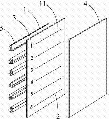
[0030] Please refer to figure 1 , figure 1 It is a structural schematic diagram of a spinal segment NMR positioning marker of the present invention, that is, the state when it is not in use. Please refer to figure 2 , figure 2 yes figure 1 exploded diagram. The described spinal segment NMR positioning mark is provided with a film 1, and the film 1 is rectangular, and is provided with an adhesive surface 11, and six marking lines 2 are printed on the adhesive surface 11, and each marking line 2 is connected with the adhesive film. The short sides of 1 are parallel, and the distances between the marking lines 2 are equal, and the marking numbers 3 are arranged on the sides of the marking lines 2, and the marking numbers 3 are Arabic numerals " 1", "2", "3", "4", "5", "6". The adhesive surface 11 of the sticking film 1 is also pasted and covered with release paper 4 . The reverse side of the viscous surface 11 of the sticking film 1 is provided with six display tubes 5, ...

Embodiment 2

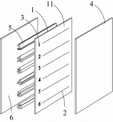
[0034] Please refer to figure 2 , figure 2 It is another exploded view of the spinal segment nuclear magnetic resonance positioning marker of the present invention. The spinal segment nuclear magnetic resonance positioning mark of this embodiment is basically the same as that of Embodiment 1, the only difference is that: the reverse side of the contact surface between the display tube 5 and the sticking film 1 is covered with a protective layer 6, and the protective layer 6 The shape is consistent with the film 1. The main function of the protective layer 6 is to protect the display tube 1 from compression deformation and from being punctured or crushed. It can be prepared from materials that do not appear in MRI, such as plastic or silica gel, preferably softer materials such as silica gel. Can adapt to the physiological curvature of the spine.

[0035] The use method and principle of the spinal segment nuclear magnetic resonance positioning marker of the present invention...


PUM


Abstract

The invention provides a positioning mark for nuclear magnetic resonance of spinal segments. The positioning mark comprises an adhesive film which is provided with a viscous surface, wherein a plurality of labeled lines which are mutually parallel are formed on the viscous surface of the adhesive film, and the viscous surface is covered by release paper in a paste mode; and display tubes in which oily liquid is filled are arranged on the other surface of the adhesive film and correspond to the positions of the labeled lines one by one, and the sections of the display tubes sequentially have shapes of Arabic numerals which are sequentially arranged. The invention has the advantages that the positioning mark can position an operative incision while the myeleterosis of a vertebral column is examined through magnetic resonance imaging (MRI); as far as a doctor is concerned, the using method is simple, can perform quick positioning, is time-saving and labor-saving, and particularly has an advantage when the pathological change of a thoracic segment of the vertebral column is positioned; as far as a patient is concerned, the X-ray radiation can be reduced, and the medical cost is saved; and meanwhile, the positioning mark can perform accurate and reliable positioning, has a simple structure, is low in cost, and can be generally popularized and used.

Description

technical field [0001] The invention relates to the technical field of medical devices, in particular to a nuclear magnetic resonance positioning marker of a spinal segment. Background technique [0002] For patients with spinal cord diseases, it is necessary to use nuclear magnetic resonance (nuclear magnetic resonance, NMR or MRI) routine scans, enhanced scans, and dynamic scans before surgery to assess the extent, extent, and severity of spinal cord trauma, tumors, infections, tuberculosis, and other diseases. Adjacent structures, good and bad tumors, etc. are accurately and clearly displayed and identified, and then surgical positioning, approach selection, surgical method determination, and treatment options are performed. Accurate localization of the diseased vertebral segment is a prerequisite for successful surgery. For example, in the operation of implanting steel plates for spinal deformation, if the wrong vertebra is placed, it will directly lead to the failure o...

Claims


Application Information

Patent Timeline
Patent Type & Authority Applications(China)
IPC IPC(8): A61B5/055
Inventor 郑学胜
Owner XIN HUA HOSPITAL AFFILIATED TO SHANGHAI JIAO TONG UNIV SCHOOL OF MEDICINE
Why Eureka
Try Eureka