Novel efficient pulverized coal combustion device

A high-efficiency technology for pulverized coal combustion, applied in the combustion method, combustion control, combustion equipment and other directions, can solve the problems of unreasonable ventilation layout, partial flame, multiple ignition, etc. Effects of large swirl duct air volume, expanded diameter and length

Inactive Publication Date: 2012-11-07
南阳市沧田工程机械有限公司
View PDF11 Cites 0 Cited by
  • Summary
  • Abstract
  • Description
  • Claims
  • Application Information

AI Technical Summary

Problems solved by technology

Before the burner is ignited, it needs to be ignited manually with a torch, and the fuel is ignited by coal powder. Due to the large difference in coal quality in various parts of our country, the success rate of ignition is relatively low, and the risk is high, and often The torch needs to be lit many times, which is extremely inconvenient to operate
Moreover, the existing pulverized coal burner is easy to cause local burning loss during use, the furnace life is short, the combustion is insufficient, the flame is seriously biased, the slag is difficult to clean, and the slagging is serious
In order to solve the problem of local slagging and burning, the furnace adopts a rotating method to avoid local long-term heating damage, but the fundamental cause of slagging and burning is unreasonable ventilation layout, insufficient pulverized coal combustion, and flame deviation. , only changing the way of rotating the furnace cannot fundamentally solve the problem of slagging and burning

Method used


Image

  • Novel efficient pulverized coal combustion device
  • Novel efficient pulverized coal combustion device

Examples


Embodiment Construction

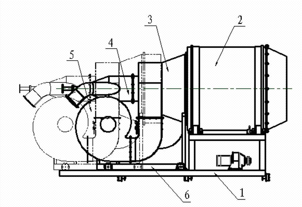
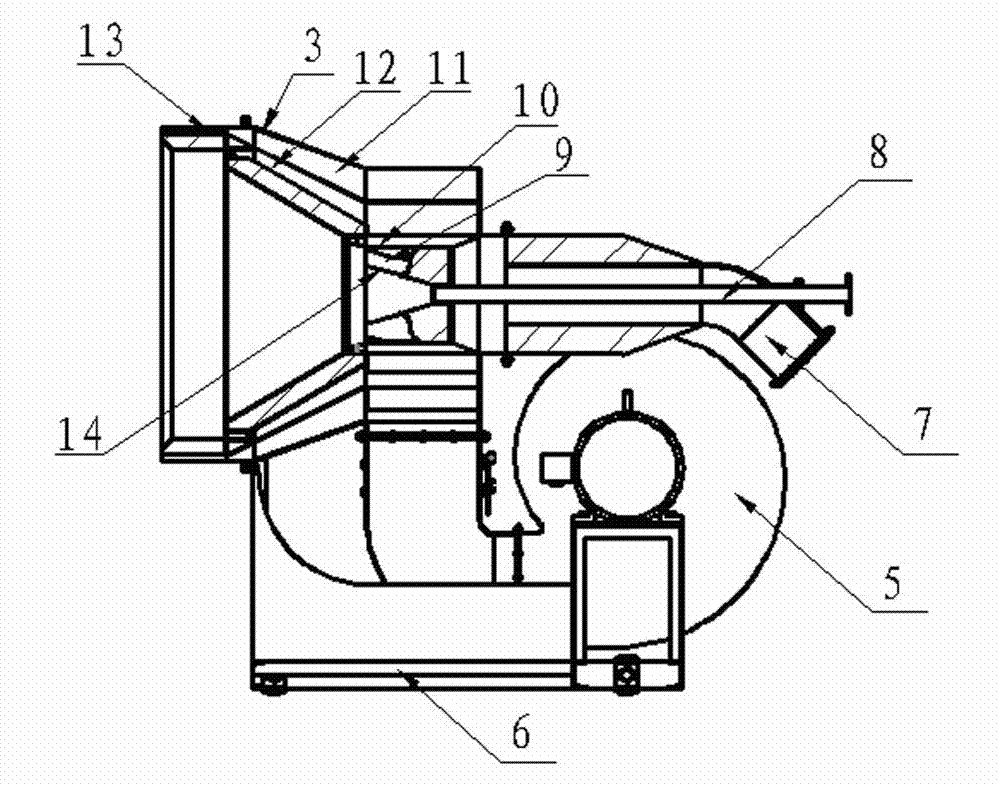
[0012] Such as figure 1 The new high-efficiency pulverized coal combustion device shown has a bottom frame 1, a furnace 2, a stable combustion chamber 3, an air powder adjustment mechanism 4, a fan 5, an ignition device and an electrical control system. The furnace 2 is placed on the bottom frame 1, and the stable combustion A part of the chamber 3 is embedded in the furnace body, and the stable combustion chamber 3 is connected with the wind powder regulating mechanism 4 and the ignition device. Such as figure 2 The air powder regulating mechanism 4 shown is provided with an outer DC air duct 11, a swirling air duct 12, an inner DC air duct 10, a pulverized coal air duct 7, and a central pipe 8 from the outer layer inward, and the fan 5 is connected to the outer DC air duct. 11. The swirl air channel 12 communicates with the inner direct air channel 10 . The outlet end of the outer DC air duct 11 is provided with long-distance DC blades 13, and the swirl air duct is provi...


PUM


Abstract

The invention discloses a novel efficient pulverized coal combustion device, which comprises a bottom frame, a hearth, a stable combustion chamber, an air powder adjusting mechanism, a fan, an ignition device and an electric control system, wherein the air powder adjusting mechanism is sequentially provided with an outer direct flowing air flue, a cyclone passage, an inner direct flowing air flue, a pulverized coal air flue and a central pipe from an outer layer to an inner layer; the fan is communicated with the outer direct flowing air flue, the cyclone passage and the inner direct flowing air flue; and a direct flowing blade is arranged at the outlet end of the outer direct flowing air flue, a cyclone blade is arranged in the cyclone passage, a plurality of direct flowing blades are uniformly arranged at the outlet of the inner direct flowing air flue, the central pipe is conical at the outlet position, a plurality of bent blades are uniformly arranged at the outlet of the pulverized coal air flue, and the inner edges of the bent blades are matched with the conical shape of the end of the central pipe. The device has the characteristics of compact structure, full combustion of pulverized coal, high coal adaptability, long service life and convenience in ignition, and can meet various heating requirements in the road building industry.

Description

technical field [0001] The invention belongs to the technical field of burners, and in particular relates to a novel high-efficiency pulverized coal combustion device used in the road construction industry. Background technique [0002] At present, there are basically a variety of combustion devices used in the road construction industry in my country. Gas (natural gas) burners, oil burners and pulverized coal burners are more common. Gas burners are limited by local resources. It cannot be applied in some places. With the rising price of fuel oil, pulverized coal burners are more popular with users because of their convenient purchase and low cost of use. Existing pulverized coal combustion devices on the market are composed of pulverizers, coal conveying pipes, burners, fuel oil ignition systems and control systems. Before the burner is ignited, it needs to be ignited manually with a torch, and the fuel is ignited by coal powder. Due to the large difference in coal quality...

Claims


Application Information

Patent Timeline
Patent Type & Authority Applications(China)
IPC IPC(8): F23C7/00F23N1/02
Inventor 王鹏钊
Owner 南阳市沧田工程机械有限公司
Why Eureka
Try Eureka