Combined-type thermal-oxidation igniting process nozzle for gasifying solid powder fuel

A technology for fuel gasification and process burner, which is applied in the direction of granular/powder fuel gasification, burner, lighting and heating equipment, etc. The effect of prolonging the service life and simplifying the ignition process of the gasifier

Active Publication Date: 2012-11-07
SHANGHAI BOILER WORKS
View PDF12 Cites 26 Cited by
  • Summary
  • Abstract
  • Description
  • Claims
  • Application Information

AI Technical Summary

Problems solved by technology

The powder fuel is usually sent into the gasifier through the central channel, and the oxygen-enriched gas (gasification agent) is sent into the gasifier through the annular channel. Due to the high temperature generated by the combustion, the maximum flame temperature exceeds 2000 ° C. The burner is subjected to high temperature, The double test of high pressure, the front end of the burner has withstood the harsh working conditions of high heat flux and oxygen-rich corrosive environment. Whether it is coil cooling or jacket cooling process, the burner head adopts jacket cooling process, the high heat flux of the head makes the thermal stress on the front wall of the burner larger, and there is a greater risk of stress damage to the front end of the burner

Method used


Image

  • Combined-type thermal-oxidation igniting process nozzle for gasifying solid powder fuel
  • Combined-type thermal-oxidation igniting process nozzle for gasifying solid powder fuel
  • Combined-type thermal-oxidation igniting process nozzle for gasifying solid powder fuel

Examples


Embodiment Construction

[0031] In order to make the present invention more comprehensible, a preferred embodiment is described in detail below with accompanying drawings.

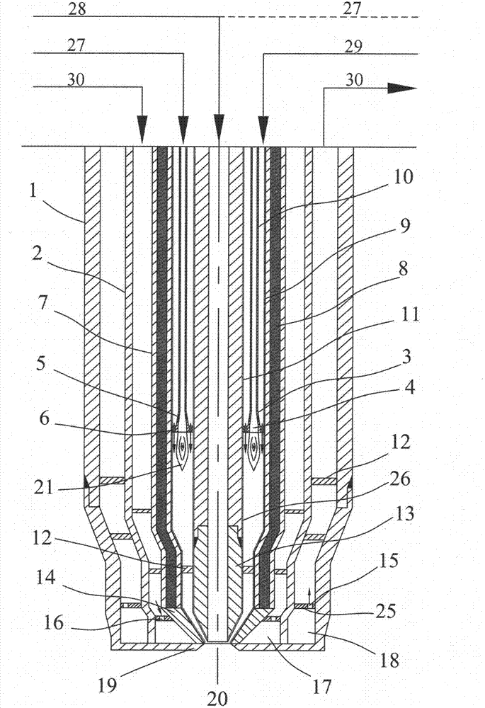
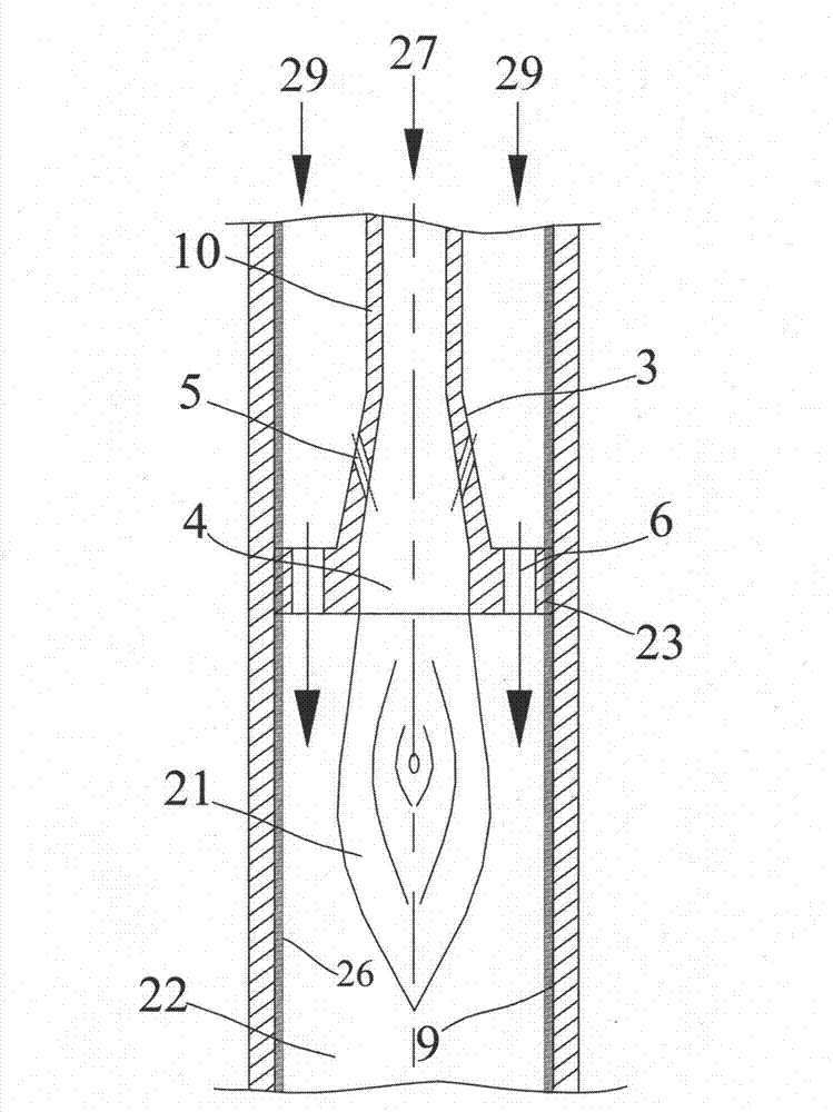
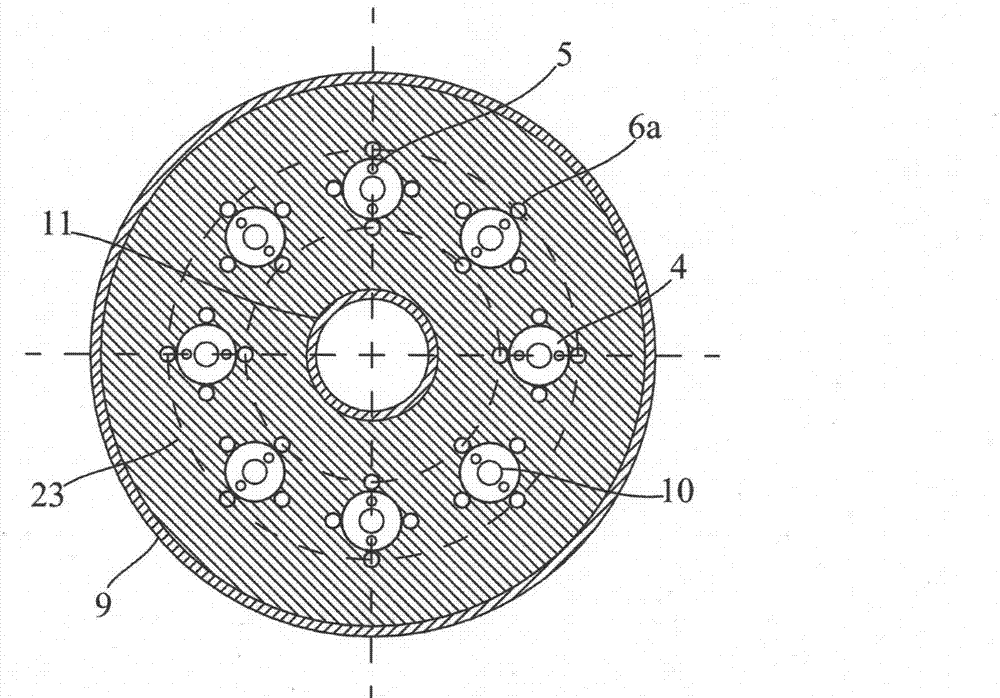
[0032] figure 1 A schematic diagram of the axial section structure of a composite thermal oxygen ignition process burner for the gasification of solid powder fuel provided by the present invention. The gasification burner for solid powder fuel includes a central channel 11 and a burner nozzle 20 The central nozzle 13 is located at the lower end of the central passage 11; 2 to 16 hot oxygen spray gun fuel passages 10 are uniformly installed outside the central passage 11 in a ring, and the outer wall 3 of the hot oxygen spray gun fuel passage 10 is provided with 2 to 10 side gasification agents Inlet 5, thermal oxygen spray gun fuel channel 10 is equipped with thermal oxygen spray gun burner 4 inside, the head of thermal oxygen spray gun burner 4 is provided with edge plate 23, has 2~12 gasification agent spouts 6 on the edge plate...


PUM

PropertyMeasurementUnit
thicknessaaaaaaaaaa
thicknessaaaaaaaaaa

Abstract

The invention provides a combined-type thermal-oxidation igniting process nozzle for gasifying solid powder fuel. The combined-type thermal-oxidation igniting process nozzle for gasifying the solid powder fuel is characterized by comprising a central passage, a thermal-oxidation spray gun fuel passage circularly shaped is uniformly arranged outside the central passage, a side gasifying agent inlet is reserved on the outer wall of the thermal-oxidation spray gun fuel passage, a thermal-oxidation spray gun burner is arranged inside the thermal-oxidation spray gun fuel passage, and a gasifying agent spraying nozzle is arranged on the head portion of the thermal-oxidation spray gun burner. An outer metal wall of a thermal-oxidation passage coaxial with the central passage is arranged outside the thermal-oxidation spray gun fuel passage, an inner metal wall of a cooling jacket is coaxially arranged outside of the outer metal wall of the thermal-oxidation passage, and an outer metal wall of the cooling jacket is coaxially arranged outside the inner metal wall of the cooling jacket via a middle tube wall of the cooling jacket. By the aid of the combined-type thermal-oxidation igniting process nozzle for gasifying the solid powder fuel, defects in the prior art are overcome, a start working nozzle and the process nozzle are integrated, and the whole igniting process of a gasification furnace is simplified. The combined-type thermal-oxidation igniting process nozzle for gasifying the solid powder fuel has the advantages of multiple functions, wide applications, long service life and the like.

Description

technical field [0001] The invention relates to a compound thermal oxygen ignition process burner for solid powder fuel gasification, belonging to the technical field of process burners. Background technique [0002] The early thermo-oxygen combustion technology was applied in the iron and steel industry and a small amount of pulverized coal furnace generator sets. For example, the US patent US3661561 applied the thermo-oxygen technology to the blast furnace aluminum smelting, raising the oxygen to above 1000 °C. U.S. Patent US4928605 built a thermal oxygen spray gun burner into the fuel burner to form an internal mixing fuel burner, which can be used as a burner for a pulverized coal furnace, which uses thermal oxygen technology to form a stable pulverized coal combustion flame . Chinese patent CN200980125201.1 proposes a thermal oxygen generating device, which uses a central channel to install a flame-retardant nozzle to heat the oxygen in the annulus to provide high-temp...

Claims


Application Information

Patent Timeline
Patent Type & Authority Applications(China)
IPC IPC(8): F23D17/00C10J3/48
CPCY02E20/34
Inventor 倪建军李月华
Owner SHANGHAI BOILER WORKS
Why Eureka
Try Eureka