Ultrasonic scanning device and method for detecting R region of inner cavity of composite material structure

A composite material and scanner technology, which is applied in the analysis of materials, the analysis of solids using sonic/ultrasonic/infrasonic waves, and the material analysis using sonic/ultrasonic/infrasonic waves, which can solve missed detection and misjudgment, influence discrimination and qualitative analysis , the signal law is not clear and other problems, to improve the stability and reliability, improve the stability of the detection signal, improve the effect of sound wave coupling

Active Publication Date: 2012-11-07
BEIJING AERONAUTICAL MFG TECH RES INST
View PDF8 Cites 17 Cited by
  • Summary
  • Abstract
  • Description
  • Claims
  • Application Information

AI Technical Summary

Problems solved by technology

[0004] (1) At present, the ultrasonic probes used in the R area of ​​the inner cavity of composite materials and other integral structures have outstanding shortcomings: (a) the blind area of ​​surface detection is large, usually above 0.8-1mm; (b) the quality of the acoustic signal from the ultrasonic probe Not high, the signal law is not clear, affecting defect discrimination and qualitative analysis; (c) low resolution
[0005] (2) For the closed inner cavity R area of ​​composite materials and other integral structures, ultrasonic scanning detection methods are mainly used at present. One method is to extend the ultrasonic probe to the closed internal cavity R of the overall structure of composite materials such as composite materials through rigid mechanical linkages. By operating the mechanical connecting rod, the ultrasonic probe can scan and detect the r-zone of the closed inner cavity of the overall structure of the composite material to be tested. Due to the complexity and the change of surface curvature, it is difficult to control the ultrasonic probe through the external rigid connecting rod, and it is difficult to ensure a stable acoustic coupling between it and the surface of the R area of ​​the inner cavity to be tested, resulting in the transmission / reception signal of the ultrasonic probe. Seriously unstable, which affects the reliability of the test results; (b) During the scanning process, through the external rigid connecting rod, it is difficult to ensure that the posture and position of the probe follow the stable surface tracking of the R area of ​​the closed inner cavity to be detected, thus affecting ultrasonic testing The reliability of the results; another method is to detect the R zone of the inner cavity from the open outside of the overall structure of the composite material. The echo signal in the R area, resulting in missed detection in the R area of ​​the inner cavity
[0006] (3) For the inner cavity R area of ​​the short-stroke composite material structure with a large internal space and regularity, there are currently special detection devices designed to install the ultrasonic probe on the scanning mechanism, and realize the change of the angle of the ultrasonic probe by controlling the scanning structure Try to make the sound wave incident direction of the ultrasonic probe consistent with the radial direction of the R zone of the inner cavity of the composite material structure as much as possible during the scanning process, so as to obtain effective ultrasonic detection signals and realize the ultrasonic detection of the R zone of the inner cavity of the overall structure. Yes: A special water spray system is required to achieve stable acoustic coupling, and the technology is expensive. For most overall structures, due to reasons such as accessibility, site, and environmental conditions, it is difficult to realize the closed inner cavity R area of ​​composite engineering structures. Automatic scanning detection, and in this method, the ultrasonic probe is usually installed in a cantilever state. The vibration of the ultrasonic probe during the scanning process will significantly affect the stability and quality of the detection signal, which may easily cause missed detection and misjudgment

Method used


Image

  • Ultrasonic scanning device and method for detecting R region of inner cavity of composite material structure
  • Ultrasonic scanning device and method for detecting R region of inner cavity of composite material structure
  • Ultrasonic scanning device and method for detecting R region of inner cavity of composite material structure

Examples


Embodiment

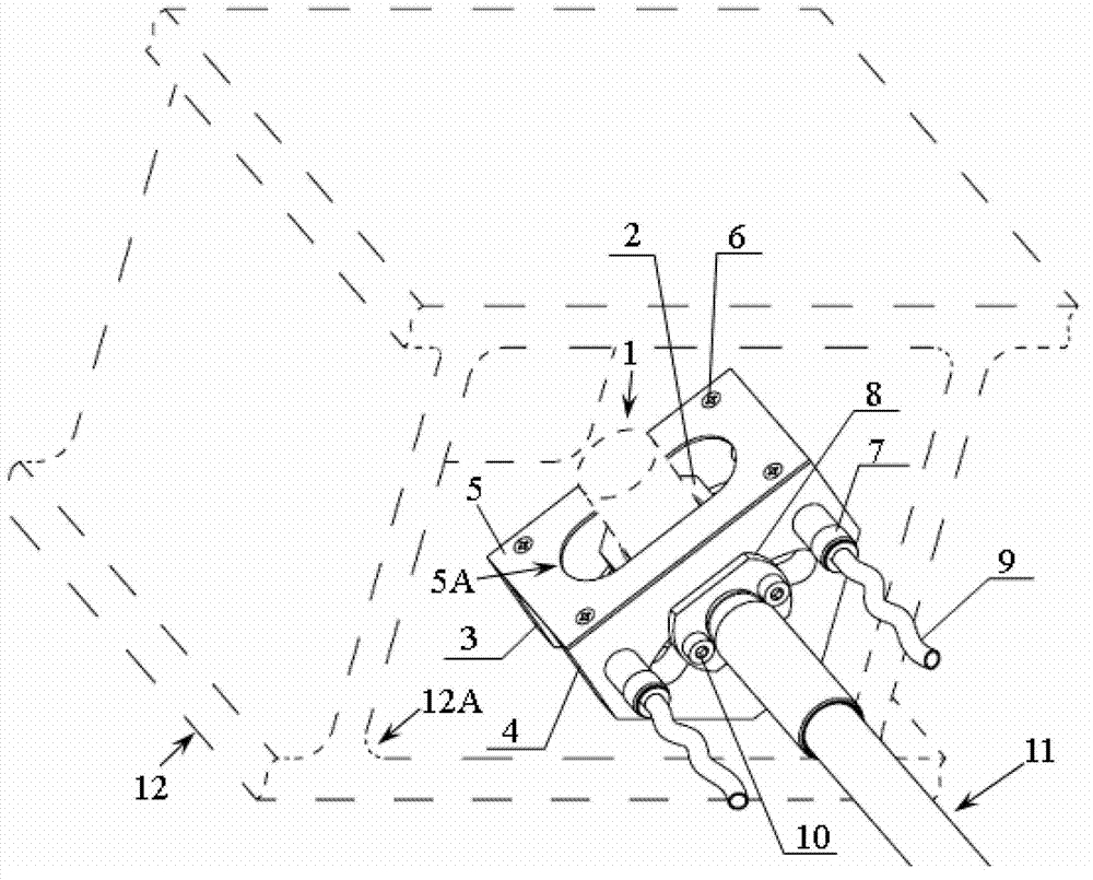
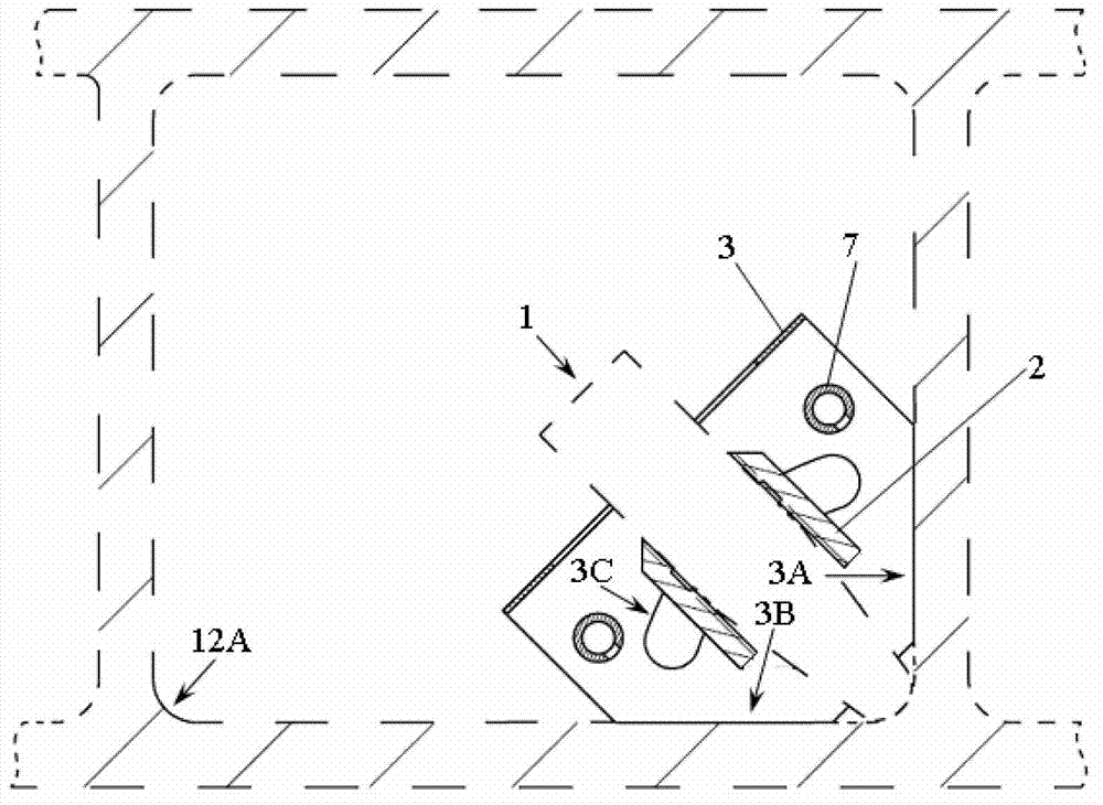
[0053] Adopt the ultrasonic probe in the closed inner cavity R region of the detection composite material structure in the present invention, select FCC-B-1, FCC-D-1 and MUT-1 in the FCC and MUT series ultrasonic instruments produced by Beijing Aeronautical Manufacturing Engineering Research Institute. Two types of ultrasonic instruments are respectively matched with the ultrasonic scanner in this patent invention, and the composite material structure closed inner cavity R area ultrasonic scanning detection method in the present invention is used to composite the aircraft with a length between 1000-2800mm respectively. A series of actual ultrasonic scanning tests were carried out on the R area of ​​the closed inner cavity of the overall structure of the material. During the scanning process, the ultrasonic probe was always in good contact with the surface of the R area of ​​the inner cavity of the overall structure of the composite material to be tested, and the detection signal...


PUM

PropertyMeasurementUnit
lengthaaaaaaaaaa
lengthaaaaaaaaaa

Abstract

The invention belongs to nondestructive testing technologies of composite materials and relates to an ultrasonic scanning device and an ultrasonic scanning method for detecting an R region of an inner cavity of a composite material structure. The ultrasonic scanning device comprises an R region ultrasonic probe, an ultrasonic probe mounting seat, a rear guide plate, a front guide plate, a cover plate, a connecting screw, a connecting column, a connector, hoses, connecting bolts and an operating rod; and the ultrasonic scanning method comprises the following steps of: mounting the R region ultrasonic probe in the ultrasonic probe mounting seat, so that the front end of the R region ultrasonic probe is contacted with the surface of the detected R region; connecting the hoses with an external water supply loop; and connecting the R region ultrasonic probe with an external ultrasonic detection instrument, driving the R region ultrasonic probe to make scanning movement along the length direction of the inner cavity of the composite material structure through the operating rod to detect the R region of the inner cavity of the composite material structure. The ultrasonic contact scanning stability and detection accessibility of the R region of the closed inner cavity of the composite material structure are greatly improved, and the reliability of a detection result is obviously improved.

Description

technical field [0001] The invention belongs to the non-destructive testing technology of structures such as composite materials, and relates to an ultrasonic scanner and a scanning method for detecting an inner cavity R area of ​​a composite overall structure. Background technique [0002] The overall structure of composite materials is an important engineering structure designed and adopted in the fields of aviation, aerospace, civil aviation, electronics, weapons, ships, electric power, etc., and is usually designed with internal cavity or internal hole structure characteristics. Since such structures are usually load-bearing structures, 100% non-destructive testing is required in engineering. However, due to the closedness and inaccessibility of the inner cavity of this kind of integral structure, it is usually difficult to realize non-destructive testing for it. [0003] At present, the ultrasonic method is mainly used to realize the non-destructive testing of the inne...

Claims


Application Information

Patent Timeline
Patent Type & Authority Applications(China)
IPC IPC(8): G01N29/04G01N29/06G01N29/24G01N29/265
Inventor 刘松平白金鹏刘菲菲李乐刚孟秋杰曹正华史俊伟傅天航
Owner BEIJING AERONAUTICAL MFG TECH RES INST
Why Eureka
Try Eureka