Method and equipment for eliminating iron scraps from raw materials

A technology of iron filings and raw materials, applied in the field of magnetic separation, can solve the problems of reduced iron removal efficiency, increased chance of scraping, and long iron removal time, so as to reduce iron removal time, weaken grinding degree, and improve iron absorption effect Effect

Active Publication Date: 2012-11-14
ZIBO S & N MAGNET MFG
View PDF4 Cites 19 Cited by
  • Summary
  • Abstract
  • Description
  • Claims
  • Application Information

AI Technical Summary

Problems solved by technology

[0004] 1. Due to the method of hoisting the magnetic rods, a set of hoisting mechanism is rotated to the top of each slurry drum, first the magnetic rod group is hoisted out of the slurry drum, and then the hoisting mechanism moves horizontally to the top of the iron filings tray, and then The movement of the scraper on the magnetic rod will scrape the iron filings adsorbed on the magnetic rod to the iron filing disc, which will increase the probability of collision and scratching of the magnetic rod, and long-term work will easily lead to the degaussing of the magnetic rod, thereby reducing the efficiency of iron removal. Effect
[0005] 2. Due to the use of multiple slurry cylinders, the hoisting mechanism needs to move to the top of different slurry cylinders, and every time iron removal has to go through: magnetic rod group rises—magnetic rod group moves horizontally—scraper moves down— —The horizontal return of the magnetic rod group——the process of the falling of the magnetic rod group leads to too long time for each iron removal, which reduces the iron removal efficiency
[0006] 3. Since the iron scraper moves along the length direction of the magnetic bar to scrape off the iron filings on the magnetic bar, the frequent movement of the iron scraper along the magnetic bar will easily damage the sealing ring between the iron scraper and the magnetic bar. After the ring is damaged, it needs to be stopped for replacement, which is very cumbersome and affects production
Moreover, the iron scraper structure also has the following defects: since the iron scraper is an iron plate, it will be magnetized after contacting the magnetic bar to generate another magnetic field, and the iron scraper frequently moves along the length of the magnetic bar, which will cause alternating magnetic field problem
However, there has been no ideal iron removal equipment in the prior art, which cannot meet the comprehensive performance requirements of ceramic enterprises for iron removal equipment

Method used


Image

  • Method and equipment for eliminating iron scraps from raw materials
  • Method and equipment for eliminating iron scraps from raw materials
  • Method and equipment for eliminating iron scraps from raw materials

Examples


Embodiment approach

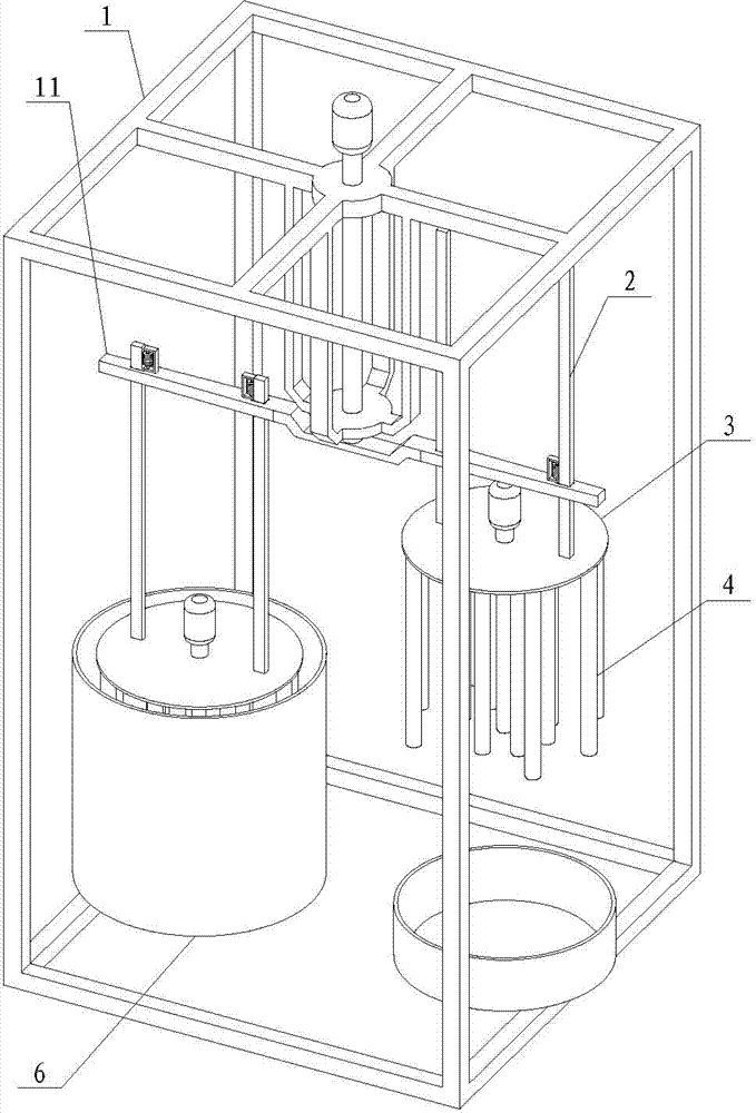
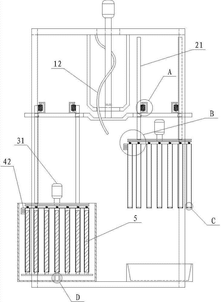
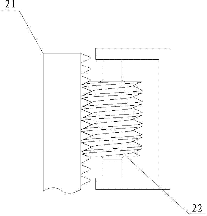
[0042] like Figures 1 to 6 As shown, a device for removing iron filings from raw materials includes a frame 1, a barrel 6, a group of magnetic rods 5 arranged in the barrel 6, a rotating arm 11 is arranged on the frame 1, and the rotating arm 11 can wind around the machine Frame 1 rotates horizontally; Lifting mechanism 2 is all set on each pivoting arm 11. The lifting mechanism 2 includes a rack 21 and a worm wheel 22 , the worm wheel 22 is arranged on the rotating arm 11 , the rack 21 meshes with the worm wheel 22 , and the lower end of the rack 21 is connected with the rotating mechanism 3 .

[0043] Motor 31, rotating disk 32 and spring 33 are set in rotating mechanism 3, and rotating disk 32 links to each other with motor 31; Spring 33 is fixed between connecting plate 41 and rotating disk 32, vibrator 42 is installed on connecting plate 41.

[0044] The iron cylinder group 4 is connected below the rotating mechanism 3, and the iron cylinder group 4 is provided with a c...


PUM


Abstract

The invention discloses method and equipment for eliminating iron scraps from raw materials. The equipment comprises a rack, a charging bucket and a group of magnetic rods, and is characterized in that rotary arms are arranged on the rack and can horizontally rotate around the rack; a lifting mechanism is arranged on each of the rotary arms; rotary mechanisms are connected to the bottoms of the lifting mechanisms; a group of iron barrels are connected to the lower parts of each of the rotary mechanisms; a connection plate, a vibrator and an iron barrel connected with the connection plate are arranged in the group of iron barrels; the group of iron barrels is driven by the lifting mechanisms to sleeve iron barrels on the magnetic rods in the group of the magnetic rods; a motor, a rotary disc and a spring are arranged in each of the rotary mechanisms; each of the rotary disc is connected with each of the motors; a spring is fixed between each of the connection plates and each of the rotary discs; and vibrators are arranged on the connection plates. The method and the equipment have the beneficial effects that the iron barrels and the magnetic rods rotate in the charging bucket when irons are attracted, so that the contact probability of the iron barrels and slurries is increased, and the iron-attraction effect is improved; and when the iron barrels are subjected to iron removal, another group of iron barrels are quickly sleeved on the magnetic rods to perform the next round of iron attraction, so that the iron removal time is shortened, and the efficiency is improved.

Description

technical field [0001] The invention belongs to the field of magnetic separation for separating solid materials from fluids, in particular to a method and equipment for removing iron filings from raw materials. Background technique [0002] In the fields of chemical industry and ceramics, liquid slurry is often used as raw material to produce solid products. Since the mineral itself contains a certain amount of iron filings, the presence of iron filings in the slurry will cause black spots in the produced floor tiles, which affects the quality of the product. In view of this, manufacturers pay more and more attention to the problem of iron removal, and put forward higher requirements for iron removal equipment. In order to obtain a high-quality iron removal effect, people initially use a manual magnetic bar iron removal process, through the adsorption of iron filings by the magnetic bar, and then manually remove the iron filings on the magnetic bar. This iron removal proce...

Claims


Application Information

Patent Timeline
Patent Type & Authority Applications(China)
IPC IPC(8): B03C1/02
Inventor 徐飞
Owner ZIBO S & N MAGNET MFG
Why Eureka
Try Eureka