Full-hydraulic self-moving type template device of vertical shaft wall

A self-moving, full-hydraulic technology, applied in shaft equipment, shaft lining, mining equipment, etc., can solve problems such as low work efficiency, template jamming, cumbersome operation, etc., and achieve the effect of convenient operation and simple structure

Inactive Publication Date: 2012-11-14
CHINA COAL MINE CONSTR GRP
View PDF6 Cites 10 Cited by
  • Summary
  • Abstract
  • Description
  • Claims
  • Application Information

AI Technical Summary

Problems solved by technology

The first one adopts the ground stabilizer suspension technology. This method takes up a lot of equipment and materials such as stabilizer and steel wire ropes. With the continuous increase of the hanging load, the technical requirements for the derrick are getting higher and higher, various technologies are approaching the limit, and the technical difficulty is becoming more and more difficult
[0003] The second is the seldom-used step-type hydraulic sliding form technology. This technology requires pre-embedded fixing devices on the permanent well wall and rock well wall every time. At the same time, it is equipped with a working platform for pouring concrete, binding steel bars for construction and disassembly. There are three platforms including the lower outrigger working platform and the operating formwork. The system is complex and the operation is cumbersome. During the upward sliding of the formwork, it is easy to cause cracks in the concrete on the shaft wall, and it is prone to deflection and jamming of the formwork. use less
[0004] The third type is the stepping hydraulically operated integral metal formwork that has not been used so far. In this technology, four beam sockets with a depth greater than 300×300mm must be reserved on all well walls at intervals of 3 to 4 meters. Performance, waterproof performance, and strength are affected to varying degrees, and three rings are set on different horizontal planes: a stepping ring, a suspension ring, and a guide ring. There is a steel wire suspension system in the vertical direction and a hydraulic system. The process is complicated and inconvenient to operate. , low work efficiency

Method used


Image

  • Full-hydraulic self-moving type template device of vertical shaft wall
  • Full-hydraulic self-moving type template device of vertical shaft wall
  • Full-hydraulic self-moving type template device of vertical shaft wall

Examples


Embodiment

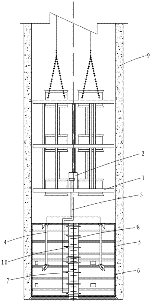
[0021] Example: Combine Figure 1-3 , the fully hydraulic self-moving formwork device for vertical shaft wall building of this embodiment, which includes:

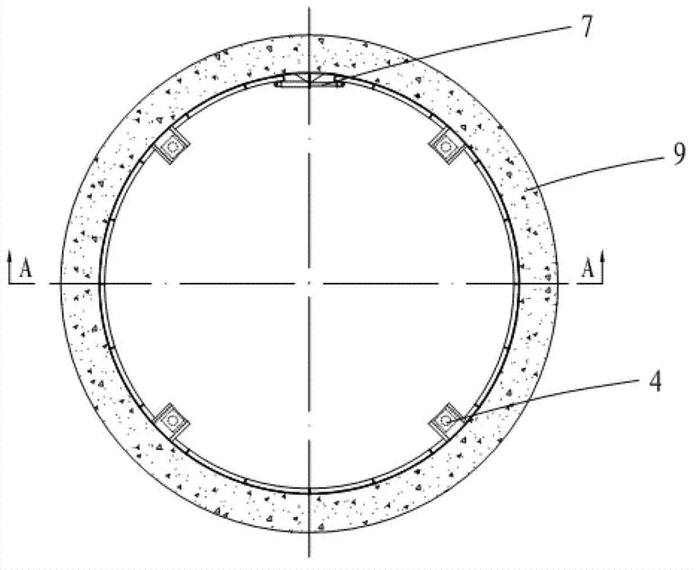
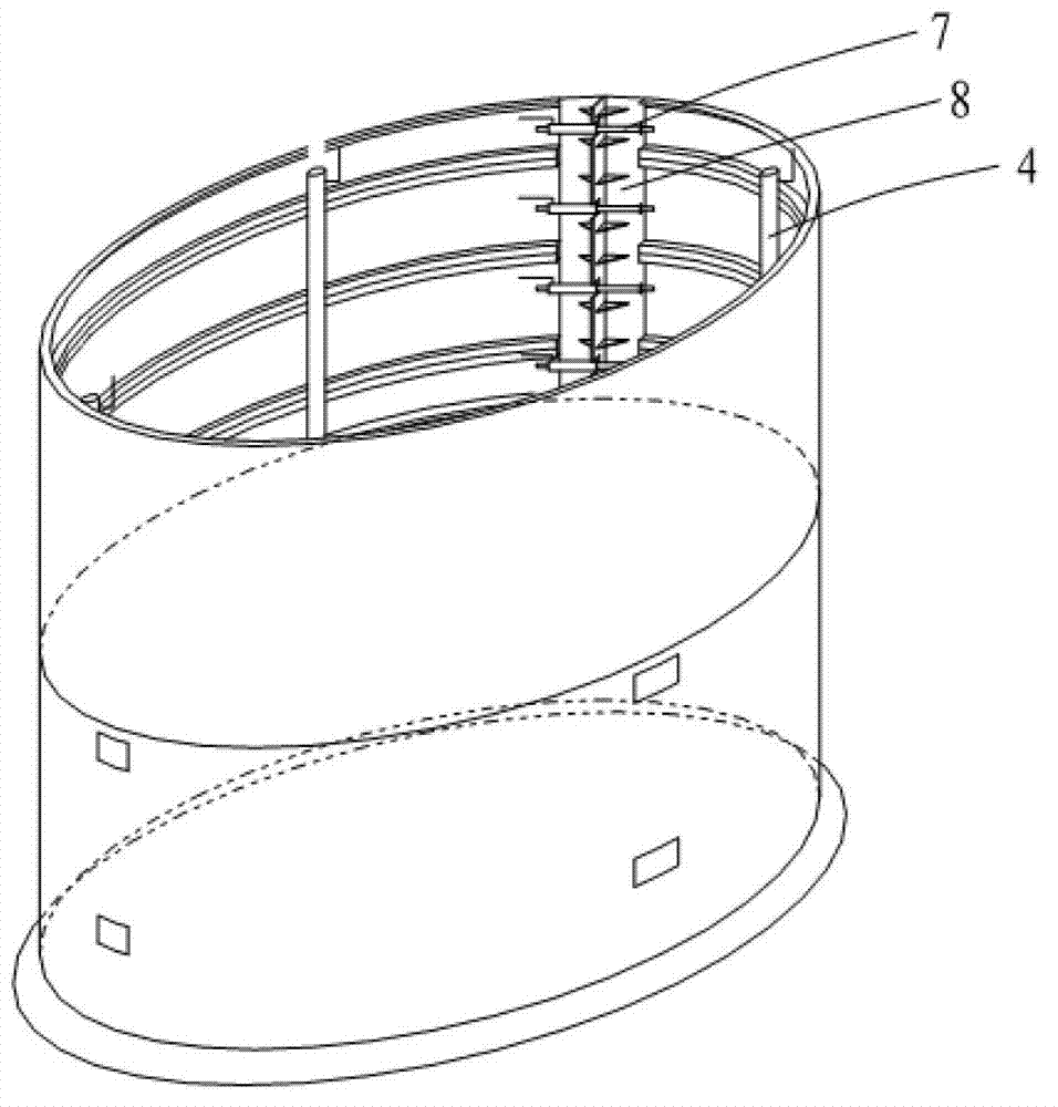
[0022] Suspension pan 1 suspended in the vertical shaft and hydraulic station 2 set on the suspension pan 1, the hydraulic station is a working room, connected with the vertical cylinder 4, the first horizontal cylinder 11 and the second horizontal cylinder 7 through the high-pressure pipeline 3 , centralized control can be realized by operating the handle, and it can also be controlled separately, and a locking structure is provided to maintain a sufficient pressure to ensure that the frictional resistance between the support structure 5 and the well wall surrounds the well wall, and the mobile formwork 6 is suspended.

[0023] In the specific arrangement, the supporting structure 5 and the movable formwork 6 are arranged under the suspension pan, the supporting structure 5 is connected with the vertical oil cylinder 4, a...


PUM


Abstract

The invention discloses a full-hydraulic self-moving type template device of a vertical shaft wall. The full-hydraulic self-moving type template device comprises a hanging scaffold which is hung in a vertical shaft, a hydraulic station which is arranged on the hanging scaffold, a vertical cylinder which is connected with the hydraulic station through a pipeline, a supporting structure which is arranged below the hanging scaffold, and a moving template, wherein the supporting structure and the moving template are respectively connected with the vertical cylinder and a piston rod of the vertical cylinder; a first horizontal cylinder which is connected with the hydraulic station through a pipeline is arranged on the supporting structure, and is used for expanding or shrinking the supporting structure, and during expanding, the first horizontal cylinder is fixed on the inner wall of the vertical shaft due to friction force and provides hanging support for the moving template; the moving template has an unclosed cylindrical shape; a second horizontal cylinder is arranged at an opening of the moving template, and a cylinder body of the second horizontal cylinder is connected to a template on one side of the opening, and the piston rod is connected to a template on the other side of the opening; and the full-automatic self-moving type template device also comprises a sealing template which is used for sealing the opening of the moving template. The full-hydraulic self-moving type template device solves the problem of hanging templates through steel wire ropes by an unstable vehicle, and realizes tunneling and concrete shaft wall supporting synchronously.

Description

Technical field: [0001] The invention relates to a fully hydraulic self-moving formwork device for vertical shaft wall building, which belongs to the technical field of mine construction. Background technique: [0002] In the rapid construction of mine vertical shaft walls, there are mainly three types of templates currently used in China. The first one adopts the ground stabilizer suspension technology, which takes up a lot of equipment and materials such as stabilizer and steel wire ropes. With the continuous increase of the hanging load, the technical requirements for the derrick are getting higher and higher, various technologies are approaching the limit, and the technical difficulty is becoming more and more difficult. [0003] The second is the seldom-used step-type hydraulic sliding form technology. This technology requires pre-embedded fixing devices on the permanent well wall and rock well wall every time. At the same time, it is equipped with a working platform f...

Claims


Application Information

Patent Timeline
Patent Type & Authority Applications(China)
IPC IPC(8): E21D5/12
Inventor 徐辉东温富城武杰秦晓光高运强刘林林刘宁方体利张宇
Owner CHINA COAL MINE CONSTR GRP
Why Eureka
Try Eureka