Flat plate soaking plate and manufacturing method thereof

A manufacturing method and vapor chamber technology, which is applied to indirect heat exchangers, lighting and heating equipment, electrical components, etc., can solve problems such as low reliability, limited heat dissipation capacity, and limited size of vapor chambers, and achieve low production costs , the effect of improving the heat dissipation capacity and ensuring the structural strength

Inactive Publication Date: 2014-03-19
北京芯铠电子散热技术有限责任公司
View PDF4 Cites 5 Cited by
  • Summary
  • Abstract
  • Description
  • Claims
  • Application Information

AI Technical Summary

Problems solved by technology

[0011] The technical problem to be solved by the present invention is to provide a flat vapor chamber, which can evenly diffuse the heat from multiple heat sources to the entire metal radiator bottom plate, maximize the heat dissipation performance of the metal radiator, and can quickly Well, the high heat flux density of the local heat source is fully diffused to the entire surface of the vapor chamber, so that the temperature of the heat source (that is, various electronic chips) is further reduced, the service life of the equipment is improved, the use efficiency of the equipment is enhanced, and the uniformity is further improved. The reliability of the hot plate, so as to overcome the shortcomings of the existing vapor chambers such as limited size, low reliability, and limited heat dissipation capacity

Method used


Image

  • Flat plate soaking plate and manufacturing method thereof
  • Flat plate soaking plate and manufacturing method thereof
  • Flat plate soaking plate and manufacturing method thereof

Examples


Embodiment Construction

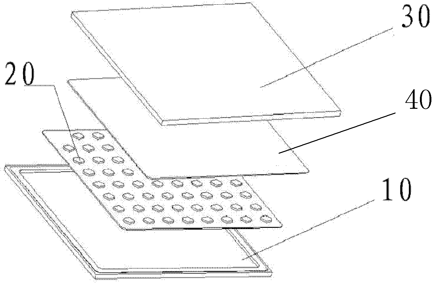
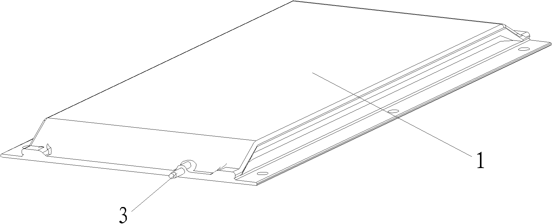
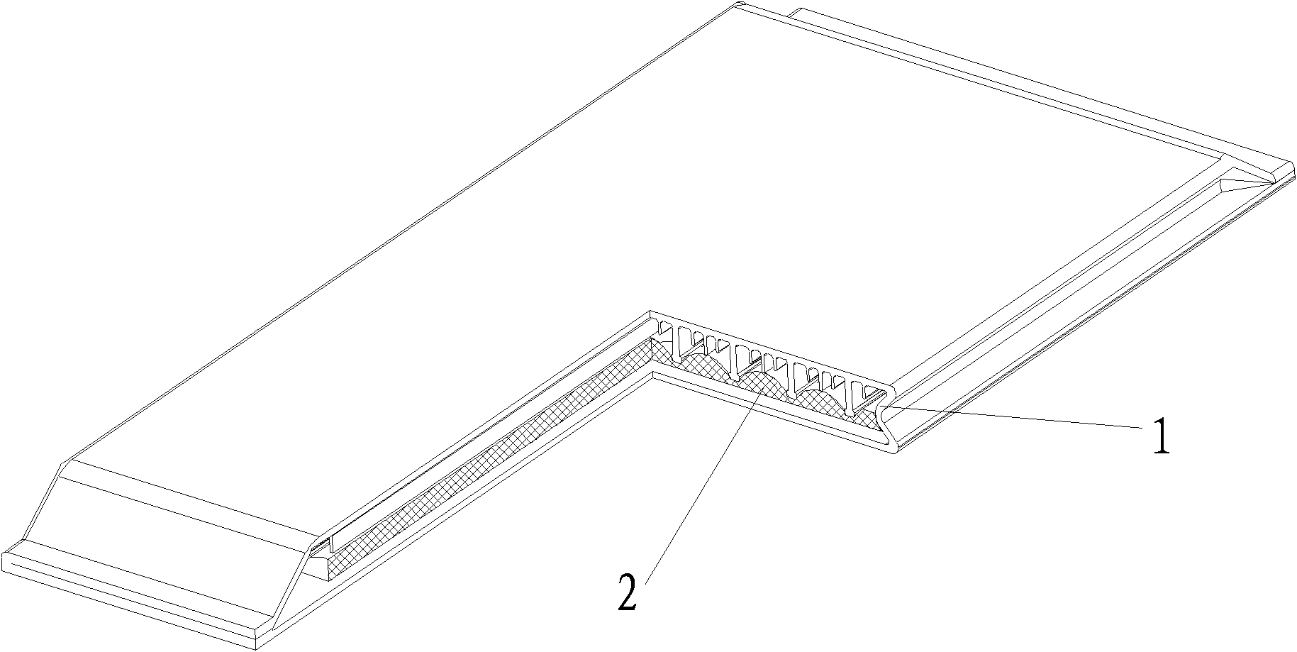
[0041] see figure 2 , image 3 As shown, the flat vapor chamber of the present invention includes: a packaging cavity 1, a porous capillary core 2 and a working fluid located inside the packaging cavity, and one end communicates with the inside of the packaging cavity 1, and the other end is located outside the packaging cavity 1 and sealed Vacuum pumping and working medium filling interface 3.

[0042] Among them, the packaging cavity 1 is preferably made of copper or aluminum. Since the thermal conductivity of copper and aluminum metal materials is good, and the copper and aluminum metal materials are conducive to machining, the packaging cavity can be made by cold extrusion or hot extrusion. 1. The strength can meet the requirements.

[0043] Please refer to Figure 4a , Figure 4b As shown, the inner upper surface of the packaging cavity 1 may be provided with structural reinforcement ribs 11 and ribs 12 for enhancing condensation and heat exchange, and the inner lowe...


PUM


Abstract

The invention relates to a flat plate vapor chamber and a manufacturing method thereof. The flat plate vapor chamber comprises a packaging chamber, a porous capillary wick, a working medium and a vacuumizing and work medium filling interface, wherein the porous capillary wire and the working medium are positioned inside the packaging chamber; one end of the vacuumizing and work medium filling interface is communicated with the inside of the packaging chamber; and the other end of the vacuumizing and work medium filling interface is positioned outside the packaging chamber and is sealed. The manufacturing method of the flat plate vapor chamber comprises the following steps of: forming the packaging chamber by extruding or casing; forming the porous capillary wick by sintering or knitting; inserting the porous capillary wick into the packaging chamber; placing one end of the vacuumizing and work medium filling interface in the packaging chamber; extruding the packaging chamber by using a cold press die; moving away the cold press die; welding and sealing a front-rear end closing surface of the packaging chamber; vacuumizing the packaging chamber and filling a working medium; and pinching off the vacuumizing and work medium filling interface and welding and sealing the vacuumizing and work medium filling interface. According to the flat plate vapor chamber disclosed by the invention, the defects of limited structure, high manufacturing cost, low reliability, limited heat-radiating capability and the like in a traditional vapor chamber are fully overcome.

Description

technical field [0001] The invention relates to a heat dissipation product, in particular to a flat soaker plate used for heat dissipation of communication equipment and photoelectric equipment and a manufacturing method thereof. Background technique [0002] In communication equipment, there are multiple heat sources on a motherboard, and the power is not low. Of course, the main reason is that the RF power amplifier has a relatively high heating power. Regarding the arrangement of these electronic devices on the circuit board and the combination of the heat sink, Often confuses electronics engineers as well as thermal design engineers. The current radiator is an aluminum profile radiator (mainly obtained by aluminum extrusion). Due to the high reliability requirements of communication equipment, the heat dissipation of general communication equipment rarely uses forced convection cooling by fans, and most of them use natural convection cooling of air. The heat dissipation...

Claims


Application Information

Patent Timeline
Patent Type & Authority Patents(China)
IPC IPC(8): F28D15/04B23P15/26H01L23/427
CPCH01L2924/0002
Inventor 李骥
Owner 北京芯铠电子散热技术有限责任公司
Why Eureka
Try Eureka