
Practical, safe and effect-producing universal control electric appliance

A general control and electrical technology, applied in the general control system, program control, computer control, etc., can solve the problems of not being able to cut off the load power supply in time, the open circuit of the limit setting end out of control, and the use of safety hazards, etc., to achieve a strong and comprehensive anti-out-of-control capability , improve safety performance, and have a wide range of effects

Inactive Publication Date: 2012-11-14
刘圣平
View PDF5 Cites 4 Cited by
  • Summary
  • Abstract
  • Description
  • Claims
  • Application Information

AI Technical Summary

Problems solved by technology

[0003] The invention mainly solves the technical problems that the original over-limit control and timing control circuits (collectively referred to as the main control circuit) often lose control due to abnormal faults, cannot cut off the load power supply in time, and has potential safety hazards; it provides a fault protection control function, It can detect abnormal faults and cut off the load power supply in time to ensure that the main control circuit does not go out of control, avoid serious accidents (such as fire or pressure explosion), and ensure the use of safe and effective general control appliances
[0004] The present invention simultaneously solves the technical problems of the input / output terminal and the limit setting terminal of the original circuit realizing the over-limit control function being out of control and the short circuit between the ports is out of control; A safe and effective universal control device for short-circuit out of control

Method used


Image

  • Practical, safe and effect-producing universal control electric appliance
  • Practical, safe and effect-producing universal control electric appliance
  • Practical, safe and effect-producing universal control electric appliance

Examples


Embodiment 1

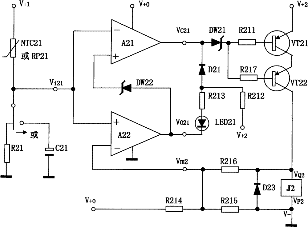
[0025] The specific circuit schematic diagram of this embodiment, as figure 2As shown, the sensing or integrating circuit (1) includes a thermistor NTC21 and a resistor R21, or a resistor Rp21 and a capacitor C21, the over-limit negative feed main control circuit (2) includes an integrated operational amplifier or a voltage comparator A22, and the over-limit protection monitoring The circuit (3) includes an operational amplifier or a voltage comparator A21 and a zener diode DW22, and the drive execution switch circuit (5) includes triodes VT21, VT22, a zener diode DW21, resistors R211, R217, a diode D23, a relay J2, and a step-down regulator The pressure circuit (6) is an existing conventional circuit, and the bottom protection display circuit (7) includes a light-emitting diode LED21, a diode D21, resistors R212, R213, and the upper and lower limit setting circuit (8) includes resistors R214, R215, and R216.

[0026] figure 2 Circuit connection mode: one end of the thermis...

Embodiment 2

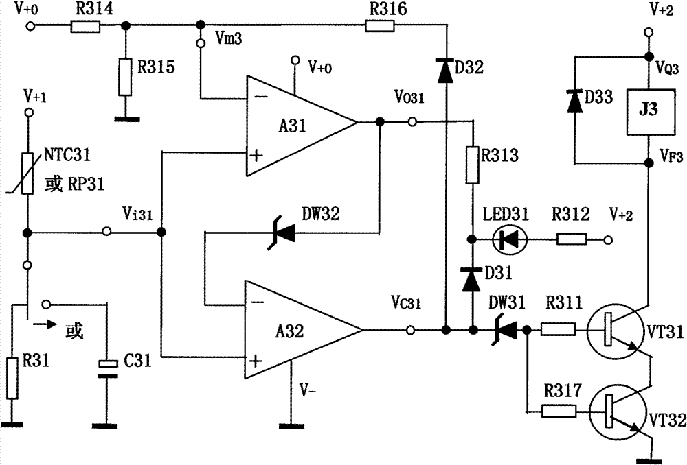
[0034] The specific circuit schematic diagram of this embodiment, as image 3 As shown, the sensing or integrating circuit (1) includes a thermistor NTC31 and a resistor R31, or a resistor Rp31 and a capacitor C31, the over-limit negative feed main control circuit (2) includes an integrated operational amplifier or a voltage comparator A31, and the over-limit protection monitoring The circuit (3) includes an operational amplifier or a voltage comparator A32 and a zener diode DW32, and the drive execution switch circuit (5) includes triodes VT31, VT32, a zener diode DW31, resistors R311, R317, a diode D33, a relay J3, and a step-down regulator The pressure circuit (6) is an existing conventional circuit, and the bottom protection display circuit (7) includes a light-emitting diode LED31, a diode D31, resistors R312, R313, and the upper and lower limit setting circuit (8) includes resistors R314, R315, R316, and a diode D32 .

[0035] image 3 Circuit connection mode: one end ...

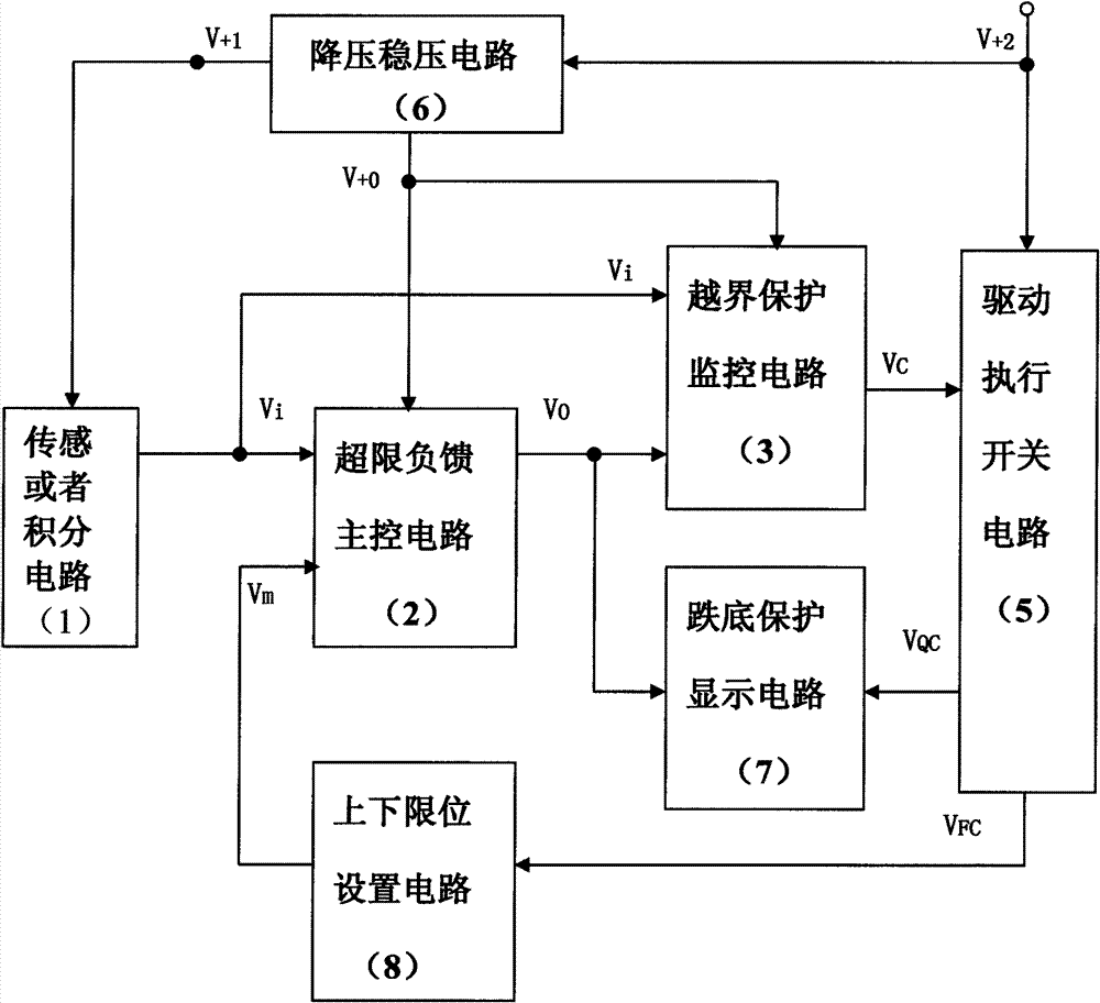
Embodiment 3

[0043] This embodiment is composed of two unit circuits parallel and complementary, wherein each unit circuit principle block diagram, such as figure 1 As shown, its specific circuit schematic diagram, such as Figure 4 As shown, the sensing or integrating circuit (1) of the first unit circuit includes a thermistor NTC41 and a resistor R41, or a resistor Rp41 and a capacitor C41, and the over-limit negative feed main control circuit (2) includes an integrated operational amplifier or a voltage comparison Device A42, cross-border protection monitoring circuit (3) includes operational amplifier or voltage comparator A41 and Zener diode DW43, bottom-fall protection display circuit (7) includes light-emitting diode LED41, diode D41, resistors R412, R413; wherein the second unit circuit The sensing or integration circuit (1) includes a thermistor NTC42 and a resistor R42, or a resistor Rp42 and a capacitor C43, the overrun negative feed main control circuit (2) includes an integrat...


PUM


Abstract

The invention belongs to a practical, safe and effect-producing universal control electric appliance in which a cross-border protection monitoring circuit carries out cross-border protection monitoring to a transfinite negative feeding main control circuit, a load power supply can be turned off when abnormal faults occur and a bottoming protection display circuit displays that the fault protection control is effective, so that a driving actuation switch circuit does not lose control. The electric appliance is applied in temperature, pressure, water level, timing control circuits and all variable measurement and control circuits, so that safety can be improved, and fire, pressure explosion and other serious accidents do not happen. Technical measures for realizing the excellent functions comprise that the cross-border protection monitoring circuit carries out the cross-border protection monitoring to the transfinite negative feeding main control circuit, the control losing signal of the main control circuit can be first turned off compulsorily when the faults happen, so that the driving actuation switch circuit does not lose control and the fault protection control is displayed to be effective. Consequently, the practical, safe and effect-producing universal control electric appliance has very wide purposes in a plurality of electronic application fields, and the product cost performance of the electric appliance is extremely high.

Description

technical field [0001] The present invention relates to a control electrical appliance, in particular to a monitoring circuit for over-limit protection for the output signal of the over-limit negative feed main control circuit for over-limit protection and monitoring, shutting down abnormal fault signals, and displaying that the fault protection control is effective by the bottom-fall protection display circuit It is a truly safe and effective general-purpose control device that ensures that the drive execution switch circuit does not go out of control (it can also turn off the load power supply in case of abnormal faults). Applied in temperature, pressure, water level, timing control and all limited variable measurement and control electrical appliances, it can improve safety performance and avoid serious accidents such as fire or pressure explosion during use. Therefore, the present invention is widely used in electronic application fields such as small household appliances ...

Claims


Application Information

Patent Timeline
IPC IPC(8): G05B19/048
Inventor 刘圣平
Owner 刘圣平
Learn More