High-voltage wire magnetic field induction energy taking device for high-voltage transmission line online monitoring

A technology of high-voltage transmission lines and high-voltage wires, which is applied in the direction of circuit devices, output power conversion devices, electromagnetic wave systems, etc., can solve problems such as incomplete shutdown, component overheating and burning, thyristor burning, etc., and achieve stability and reliability improvement , Reduce power consumption, reduce the effect of power consumption

Inactive Publication Date: 2012-11-14
NORTH CHINA ELECTRIC POWER UNIV (BAODING) +1
View PDF4 Cites 16 Cited by
  • Summary
  • Abstract
  • Description
  • Claims
  • Application Information

AI Technical Summary

Problems solved by technology

Transistors, bidirectional thyristors and other components can work stably for a long time only when they are fully turned on or completely turned off. A large amount of power consumption is generated, causing the components to overheat and burn
[0008] The problem with the control strategy of the energy harvesting device described in Chinese invention patent 201110323678.x is that the control circuit forms an analog voltage feedback, and the strength of the control signal is proportional to the output voltage of the device, that is, the control signal is an analog quantity.
Therefore, there is a problem of the strength of the control signal. First, when the current of the transmission line is at a critical value (that is, the output voltage of the coil is near the maximum output voltage value),

Method used


Image

  • High-voltage wire magnetic field induction energy taking device for high-voltage transmission line online monitoring
  • High-voltage wire magnetic field induction energy taking device for high-voltage transmission line online monitoring

Examples


Embodiment Construction

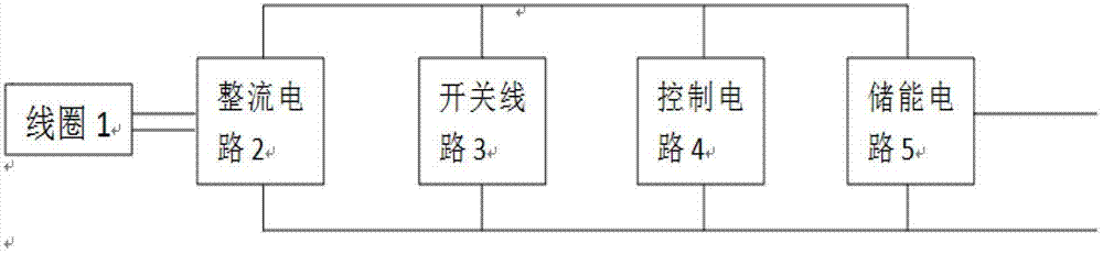
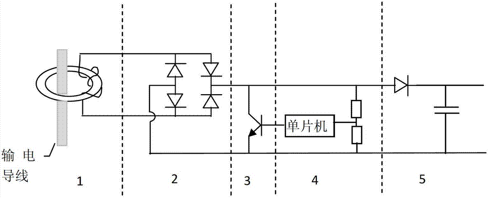
[0020] Embodiments of the high-voltage wire magnetic field induction energy harvesting device for on-line monitoring of high-voltage transmission lines of the present invention figure 2 As shown, it includes a coil 1, a rectifier circuit 2, a switch circuit 3, a control circuit 4 and an energy storage circuit 5. The coil 1 is set on a high-voltage wire, and the AC current is induced from the high-voltage wire by using the principle of electromagnetic induction and sent to the rectifier circuit 2 for rectification. The circuit 2 converts the AC current into a DC current, and charges the energy storage circuit 5, and the switch circuit 3 is connected in parallel to the output terminal of the rectifier circuit 2; the control circuit 4 detects the output voltage of the energy storage circuit, and controls the conduction and switching of the switch circuit accordingly. When it is turned off, the energy storage circuit 5 outputs voltage and current.

[0021] The energy-taking coil ...


PUM


Abstract

The invention discloses a high-voltage wire magnetic field induction energy taking device for high-voltage transmission line online monitoring. The device comprises a coil (1), a rectification circuit (2), a switching circuit (3), a control circuit (4) and an energy storage circuit (5), wherein the coil is sleeved on a high-voltage wire; alternating current is induced from the high-voltage wire and is fed to the rectification circuit by utilizing the electromagnetic induction principle, the alternating current is converted into direct current through the rectification circuit and charges the energy storage circuit, and the switching circuit (3) is connected in parallel at the output end of the rectification circuit (2); and the control circuit detects output voltage of the energy storage circuit, so that the on/off of the switching circuit is controlled, and the energy storage circuit outputs voltage and current. The application range of the energy taking device is reduced, and the power loss of the switching circuit is reduced; because the switching circuit is positioned in a switch-on state for a long time in actual use, and the magnetic induction intensity in a magnetic core of the coil is low, the power loss of the magnetic core is reduced; and because the whole power loss of the energy taking device is reduced, the service life of the device is prolonged, and the stability and the reliability of the device are greatly improved.

Description

technical field [0001] The invention relates to a wire magnetic field induction energy harvesting device, in particular to a high-voltage wire magnetic field induction energy harvesting device for on-line monitoring of high-voltage transmission lines. Background technique [0002] With the development of science and technology, various physical parameters of live detection lines are increasingly required in the field of high-voltage transmission lines. A considerable number of devices will be suspended on high-voltage transmission wires to measure physical parameters such as wire temperature and wire sag. Because these monitoring devices need to be installed directly on the high-voltage transmission line, what method to use to power the device is a problem that we need to focus on. At present, the power supply methods that are widely used mainly include solar power supply, battery power supply, magnetic field induction power supply, laser power supply, etc. The working prin...

Claims


Application Information

Patent Timeline
IPC IPC(8): H02J17/00H02M7/217H02J50/10
Inventor 程养春戴沅詹花茂窦洪齐波胡平陈凯
Owner NORTH CHINA ELECTRIC POWER UNIV (BAODING)
Why Eureka
Try Eureka