Phase contrast imaging

一种相衬成像、X射线的技术,应用在医药科学、诊断、用于放射诊断的仪器等方向,达到减少X射线剂量暴露、增加质量的效果

Active Publication Date: 2012-11-14
KONINK PHILIPS ELECTRONICS NV
View PDF2 Cites 9 Cited by
  • Summary
  • Abstract
  • Description
  • Claims
  • Application Information

AI Technical Summary

Problems solved by technology

Another disadvantage of differential phase contrast CT is that the noise power spectrum of the image has a peak in the low frequency region

Method used


Image

  • Phase contrast imaging
  • Phase contrast imaging
  • Phase contrast imaging

Examples


Embodiment Construction

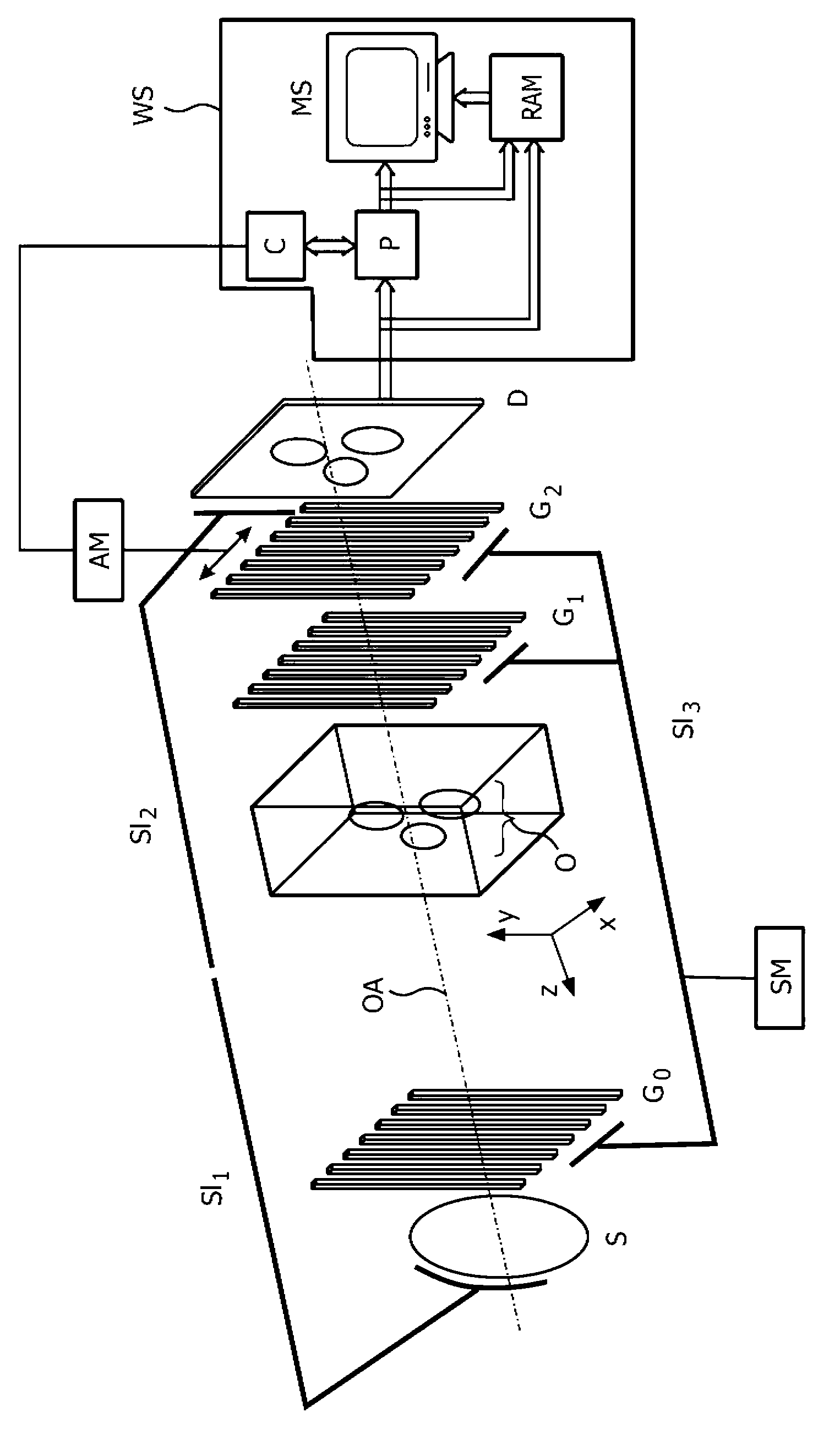
[0063] figure 1 is a schematic representation of the grating setup of a Talbot-Lau type hard X-ray imaging interferometer, which can be used in accordance with the present invention. The device will be described hereinafter in the context of a general description of the functionality of the different parts of the device.

[0064] Using such an interferometer leads to the effect that the interfering X-rays are not completely separated, but are only clipped at small angles so that they pass through different, closely spaced parts of the sample. A hard X-ray imaging interferometer includes: an incoherent X-ray source S; a source grating G for achieving spatial beam coherence 0 ; Diffraction grating G with a plurality of equidistant X-ray absorption strips extending in parallel in a direction perpendicular to the optical axis of the interferometer 1 (also referred to herein as a phase grating), the diffraction grating acts as a phase-shifting beam splitter and is placed in the d...


PUM


Abstract

X-ray devices for Phase Contrast Imaging (PCI) are often built up with the help of gratings. For large field-of-views (FOV), production cost and complexity of these gratings could increase significantly as they need to have a focused geometry. Instead of a pure PCI with a large FOV, this invention suggests to combine a traditional absorption X-ray imaging system with large-FOV with an insertable low-cost PCI system with small-FOV, The invention supports the user to direct the PCI system with reduced FOV to a region that he regards as most interesting for performing a PCI scan thus eliminating X-ray dose exposure for scanning regions not interesting for a radiologist. The PCI scan may be generated on the basis of local tomography.

Description

technical field [0001] The present invention relates to differential phase contrast imaging (PCI), and in particular, the present invention relates to apparatus and methods for differential phase contrast imaging. Background technique [0002] Conventional X-ray systems for medical applications are mainly based on the difference in absorption of X-rays in matter, resulting in projection images formed by the cumulative absorption of X-rays along a line. However, matter affects not only the absorption of X-rays but also the refraction of X-rays. This property portends higher X-ray contrast between human tissue types than conventional absorption-based imaging, and thus could represent a future improvement. One possible setup to facilitate PCI is raster based. [0003] The problem facing the use of gratings in the transmitted X-ray beam is that unfocused gratings produce less absorption modulated by the grating itself, especially outside the central region of the field of view...

Claims


Application Information

Patent Timeline
Patent Type & Authority Applications(China)
IPC IPC(8): A61B6/00G01N23/04
CPCA61B6/4441A61B6/484A61B6/00A61B6/4291
Inventor D·格勒K·J·恩格尔G·福格特米尔T·克勒E·勒斯尔
Owner KONINK PHILIPS ELECTRONICS NV
Why Eureka
Try Eureka