Self-supporting combined steel template construction method

A construction method and steel formwork technology, which is applied in the field preparation of formwork/formwork/work frame, building components, construction, etc., can solve the problems of simultaneous multi-layer construction, unfavorable floor and ceiling decoration, and occupation of turnover materials. Achieve high promotion and application value, improve the construction environment, and save materials

Active Publication Date: 2012-11-21
HANGZHOU HENGDA STEEL STRUCTURE
View PDF5 Cites 4 Cited by
  • Summary
  • Abstract
  • Description
  • Claims
  • Application Information

AI Technical Summary

Problems solved by technology

This construction method has a wide range of applications, but it needs to build a lot of scaffolding, and multiple layers cannot be constructed at the same time. The construction progress is slow, it takes up a lot of turnover materials, and the construction cost is high.
[0004] Another construction method is self-supporting formwork construction. Self-supporting formwork construction is to process the steel bars in the floor into a three-dimensional steel truss in the factory, and weld the three-dimensional steel truss and galvanized steel plate into a three-dimensional plate; Installed on steel beams and laying additional steel bars, it can bear the concrete self-weight and construction live load during the construction stage, without scaffolding support; however, when the concrete reaches a certain strength in this construction method, the formwork will be difficult to remove. The galvanized steel plate is used as a permanent formwork; from an economic point of view, the construction cost is too high; from the perspective of use, the galvanized steel plate is used as a ceiling, which is not conducive to the decoration of the floor ceiling, and the galvanized steel plate ceiling gradually becomes dark over time. Corrosion, affect the use

Method used


Image

  • Self-supporting combined steel template construction method
  • Self-supporting combined steel template construction method
  • Self-supporting combined steel template construction method

Examples


Embodiment Construction

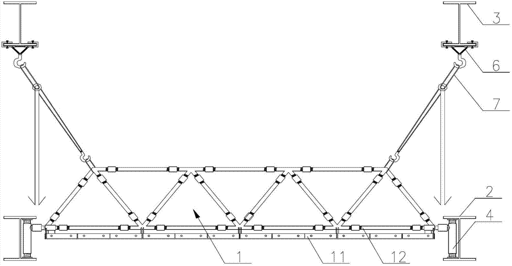
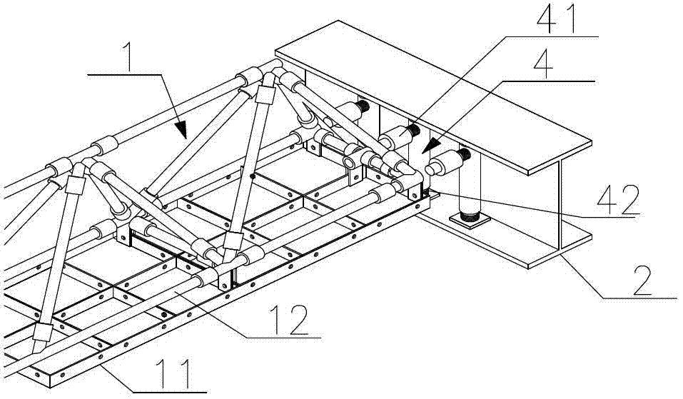
[0030] Below with the accompanying drawings Figure 1~5 And specific embodiment the present invention is described in further detail;

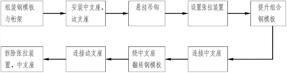
[0031] The construction method of self-supporting combined steel formwork, including assembling steel formwork and trusses, installing middle support and side supports, hanging hooks, installing tensioning devices, lifting combined steel formwork, connecting middle supports, and flipping around middle supports Steel formwork, connecting side supports, removing tensioning devices and middle supports, etc.

[0032] The specific steps are:

[0033] Assemble the steel formwork 11 and the truss 12 on the ground or platform, the steel formwork 11 is composed of stiffeners and panels, the panels are placed under the stiffeners, the steel formwork 11 is placed on the lower truss 12, forming an inverted self-supporting combined steel formwork 1 The self-supporting combined steel formwork 1 has a certain rigidity and strength; the geometric dimension ...


PUM


Abstract

The invention relates to a multi-story and high-rise mixed structure building system construction technology, and aims to provide a self-supporting combined steel template construction method. The method comprises the following steps of: integrally and inversely assembling a self-supporting combined steel template on the ground surface or a platform, and lifting the inverse self-supporting combined steel template to a specified position through a tensioning device; connecting the inverse self-supporting combined steel template with a middle supporting seat though a horizontal connecting rod, and integrally overturning the inverse self-supporting combined steel template into place around a middle supporting seat horizontal connecting rod under the action of self-gravity; realizing connection through a side supporting seat horizontal connecting rod; and during construction of a self-supporting combined steel template of a next independent unit, circularly performing the construction steps. Compared with a construction method for erecting full framing scaffolding, the method has the advantages that the template construction cost is lowered greatly, the construction speed is increased greatly, and the site construction environment is improved remarkably.

Description

technical field [0001] The invention belongs to the construction field of a multi-high-rise mixed structure building system, and in particular relates to a self-supporting composite steel formwork construction method. Background technique [0002] In recent years, multi-high-rise mixed structure buildings are increasing. The characteristics of this structural system are: (1) columns generally adopt steel columns, steel pipe concrete columns or steel-reinforced concrete columns; (2) beams generally adopt H-shaped steel beams; (3) The floor is made of cast-in-place concrete floor or composite floor; (4) The floor is equipped with primary and secondary beams, and the floor span is small. [0003] At present, the formwork of cast-in-place concrete slabs in our country generally adopts wood formwork or combined steel formwork; the wood formwork is limited in use due to the disadvantages of low material turnover rate, slow construction speed, and serious waste of wood. During the...

Claims


Application Information

Patent Timeline
Patent Type & Authority Applications(China)
IPC IPC(8): E04G11/36E04G11/48
Inventor 金海罗浩朱罗军费建伟黄功文
Owner HANGZHOU HENGDA STEEL STRUCTURE
Why Eureka
Try Eureka