Mold and its manufacturing method

A manufacturing method and mold technology, applied in coatings, instruments, optics, etc., can solve the problems of cracks in the coating layer, poor joints, hindering the flow of resin, etc., to improve surface roughness, reduce flexural deformation, fluidity, etc. good effect

Active Publication Date: 2015-12-16
HIRAI KOGYO KK
View PDF4 Cites 3 Cited by
  • Summary
  • Abstract
  • Description
  • Claims
  • Application Information

AI Technical Summary

Problems solved by technology

However, if hard chromium plating is applied to the inner wall surface of the flow path of the mold, if the lip-shaped portion is covered with cemented carbide powder, the adhesion of the hard chromium plating at the front end of the lip-shaped portion is poor. , so that cracks occur in the plating layer, which becomes one of the causes of flaws on the formed resin film
Therefore, after the coating process, after the coating layer of the thermal spraying predetermined part is peeled off by grinding process etc., when intending to carry out thermal spraying, cracks will occur at the seam between the coating part and the thermal spraying part, and It is easy to cause poor bonding and may hinder the flow of resin
In addition, in the case of covering cemented carbide powder by thermal spraying, since the superhard powder material mainly composed of WC is melted and then sprayed, grinding and lapping are performed after spraying to complete the edge. At the time, the particles of the powder material are prone to peeling or cracking

Method used


Image

  • Mold and its manufacturing method
  • Mold and its manufacturing method
  • Mold and its manufacturing method

Examples


Embodiment Construction

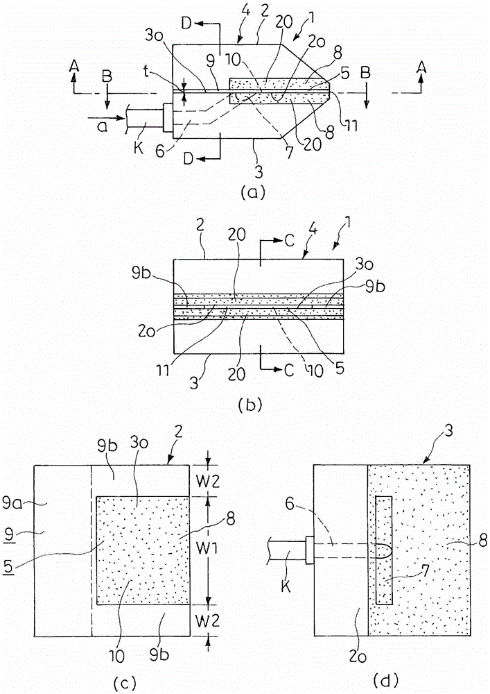
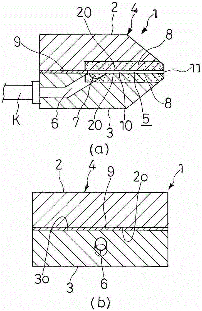
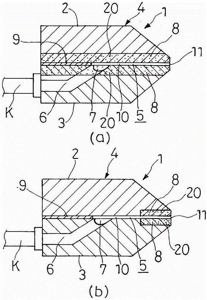
[0074] Hereinafter, a suitable embodiment of the present invention will be described according to the drawings, such as figure 1 As shown, the coating mold 1 has a mold body 4 composed of an upper mold 2 and a lower mold 3 , and a mold flow path 5 is provided between the upper and lower molds 2 and 3 . In the lower mold 3, as shown in (a) and (b) of Figure 1, the coating liquid supply path 6 that supplies the coating liquid from the outside through the supply pipe K and is supplied according to the arrow a; Once the coating liquid in the channel 6 is accumulated, a manifold 7 that expands in the mold width direction is provided. These supply paths 6 and manifolds 7 form part of the mold flow path 5 , and lip portions 8 , 8 are provided on the front end side of the mold flow path 5 .

[0075] In addition, on the joint surfaces 2o, 3o between the upper mold 2 and the lower mold 3, a base 9a, two sleeves 9b, 9b forms the inner tube 9 with a substantially U-shaped thickness t in...


PUM

PropertyMeasurementUnit
hardnessaaaaaaaaaa
hardnessaaaaaaaaaa

Abstract

The present invention relates to a mold and its manufacturing method, which is a lip-shaped part composed of a HIP layer that is directly diffusion bonded to the base material of the mold body through HIP (Hot Isopressing), wherein Densification has excellent flexural strength and toughness. While the surface roughness is completed with high precision, the edge can be completed with high precision sharp edge, thus providing a kind of material with good wear resistance and corrosion resistance. Mold for the lip. On the front end side of the mold flow path (5) formed in the mold body (4), a lip portion (8) is provided, and the coating liquid supplied to the mold flow path (5) flows from the lip portion (8) ) out of the mold, wherein at least the lip portion (8) is directly diffusion bonded to the base material of the mold body 4 by subjecting the alloy powder 19 with good corrosion resistance and wear resistance to HIP treatment The HIP layer 20 is formed.

Description

technical field [0001] The present invention relates to a mold for coating a gel-like or liquid coating solution on a walkable flexible belt-like support, or discharging molten resin for forming a resin film from the lip-like portion (painting die or T-die) and method of manufacturing the same. Background technique [0002] Conventional molds, for example, in terms of coating molds, although specific known documents such as patent publications cannot be cited as examples, in conventionally used coating molds, there is a front end of the mold flow path formed as the mold body. A mold with a lip-shaped member made of cemented carbide is installed on the side. The cemented carbide of the lip-shaped member obtains high rigidity, wear resistance, and corrosion resistance, thereby improving the accuracy of the shape of the tip. [0003] In addition, resin films manufactured by extruders using T-die are required to have no thickness variation or streak-like defects, especially for...

Claims


Application Information

Patent Timeline
Patent Type & Authority Patents(China)
IPC IPC(8): B05C5/02B22F3/15B29C47/14G02F1/13B29C48/08B29C48/305
CPCB05C5/0254B22F3/15B22F7/08B29C48/05B29C48/08B29C48/154B29C48/3003B29C48/305B29C48/30B05C5/02B29C33/38G02F1/13
Inventor 平井昌夫
Owner HIRAI KOGYO KK
Why Eureka
Try Eureka