
Face miller and use thereof

A face milling cutter and blade technology, applied in milling cutters, milling cutting inserts, cutters for milling machines, etc., can solve the problems that the cutter cannot maintain the level of cutting efficiency and tool life, milling cutter vibration, and excessive insert load, etc. Achieve good surface quality, prolong service life and reduce heat generation

Inactive Publication Date: 2012-11-21
GUEHRING OHG
View PDF11 Cites 4 Cited by
  • Summary
  • Abstract
  • Description
  • Claims
  • Application Information

AI Technical Summary

Problems solved by technology

[0004] However, the aforementioned type of face milling cutter has the following problems when the cutting speed is continuously increased: the cutting force distribution generated after the cutting edge suddenly cuts into the workpiece will cause the milling cutter to vibrate violently and cause the insert to be subjected to point-like distribution. overload
The result is often that the tool cannot maintain an adequate level of cutting efficiency and tool life

Method used


Image

  • Face miller and use thereof
  • Face miller and use thereof
  • Face miller and use thereof

Examples


Embodiment Construction

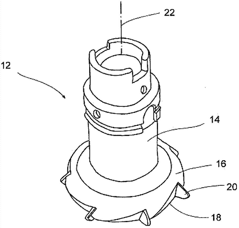
[0035] figure 1 What element symbol 12 represents in is a face milling cutter, and milling head 16 is housed on its cylindrical shank 14. Each of the grooves 18 of the milling head 16 accommodates a hard material cutting insert 20, and the specific arrangement is such that all the hard material cutting inserts 20 are located on the same indexing circle or the same edge trajectory and are spaced apart from each other by a specified distance. the circumferential distance of . Adjacent hard material cutting inserts 20 are preferably separated by different circumferential distances, that is, the milling tool adopts unequal graduations, which can reduce tool vibration caused by natural frequencies.

[0036] The above tool is a flat milling head for flat milling of end faces. The diameter of the milling head of such tools is preferably set at 1.3 times the width of the workpiece to be machined.

[0037]figure 1 The tool shown is characterized in that both the geometry of the hard...


PUM


Abstract

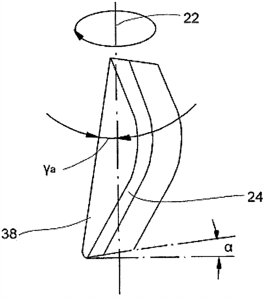
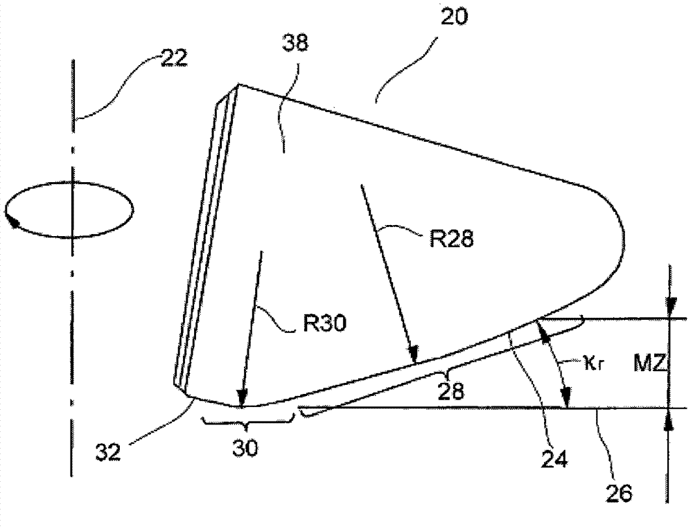
The face miller (12) is equipped with a plurality of plate-shaped hard material cutting inserts (20) that are distributed over the circumference. The hard material cutting inserts are located on a graduated circle in pockets (18) of a blade carrier (16) and have a main cutting edge (24), which is adjusted at a cutting edge angle (Kr) smaller than 90 relative to the working plane (26) of the miller. In order to ensure maximum machining performance at a good service life, the cutting edge angle (Kr) is selected to range between 10 DEG and 30 DEG, preferably between 15 DEG and 25 DEG, wherein the main cutting edge (24) at the same time has a slightly convex design. The main cutting edge (24) transitions into the secondary cutting edge (32) via a transition radius (R30) having a value that ranges between 0.5 and 1.5 mm. The axial rake angle (ya) ranges between 20 DEG and 30 DEG , preferably between 23 DEG and 27 DEG. According to an advantageous further development, the radial rake angle (yr) ranges between -6 DEG and -10 DEG, preferably between -7 DEG and -9 DEG.

Description

technical field [0001] The invention relates to a face milling cutter according to the preamble of claim 1 with a plurality of plate-shaped hard material cutting inserts distributed around its periphery. Background technique [0002] Face milling cutters of this type are often implemented as milling heads, on which a number of inserts (for example indexable inserts) made of cemented carbide, ceramic (cermet) or polycrystalline diamond (PCD) are mounted. In conventional technology, the blade is formed with an entering angle κ of about 75° r It is installed on the flat milling head in the same way, that is, the main cutting edge forms an angle κ of about 75° with the plane to be machined in a plane containing the axis of the milling cutter r . Wherein, the axis of the milling cutter is perpendicular to the surface of the workpiece, and the secondary cutting edge against the end face of the cutter produces the surface to be processed. [0003] Like cutting tools, face millin...

Claims


Application Information

Patent Timeline
Patent Type & Authority Applications(China)
IPC IPC(8): B23C5/06B23C5/18
CPCB23C2210/045B23C2210/0407B23C2210/282B23C2226/125B23C2250/12B23C2200/203B23C2224/04B23C2210/0435B23C2240/08B23C5/06B23C2210/206B23C2228/10B23C2240/21B23C2224/22B23C2224/24B23C2226/315B23C5/18B23C2210/084B23C2224/36B23C2222/04Y10T407/14Y10T407/15Y10T407/1908Y10T407/1946Y10T407/23Y10T407/26Y10T409/303752Y10T409/303808
Inventor L·博兹库尔特
Owner GUEHRING OHG
Learn More