Evaporation cooled lamp

A technology for cooling steam and lamps, which is applied to cooling/heating devices of lighting devices, lampshades, components of lighting devices, etc., and can solve problems such as LED cooling and light output life reduction

Inactive Publication Date: 2012-11-21
欧勒・K・尼尔森
View PDF8 Cites 15 Cited by
  • Summary
  • Abstract
  • Description
  • Claims
  • Application Information

AI Technical Summary

Problems solved by technology

Placing the LEDs in a diffuser housing can improve the surface brightness issue, but this also creates cooling issues for the new LEDs
As mentioned earlier, unlike incandescent bulbs, which require a very hot environment to produce light, the light output and lifespan of LEDs will decrease severely with increasing temperature

Method used


Image

  • Evaporation cooled lamp
  • Evaporation cooled lamp
  • Evaporation cooled lamp

Examples


Embodiment Construction

[0026] This invention relates to LED light fixtures (or other types of light fixtures) that use water or other coolant to evaporate inside a glass bulb to remove heat without the need for an external heat sink or connection to a heat sink.

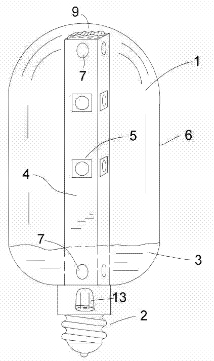
[0027] Usually the pressure inside the fixture is reduced to lower the boiling point of the coolant. figure 1 An example of such a luminaire is shown.

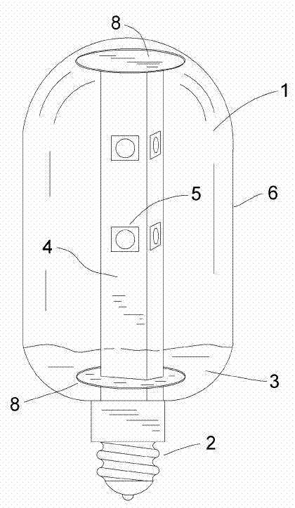
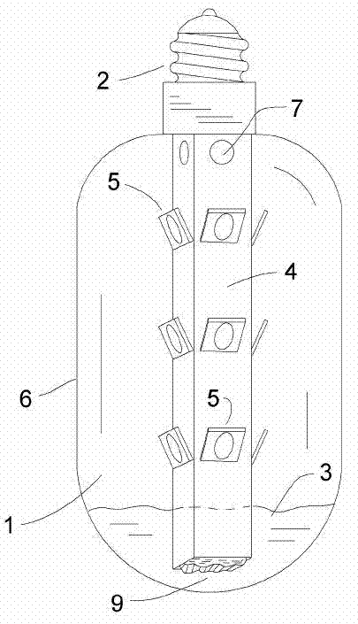
[0028] The glass bulb 6 contains a support structure 4 or light pole for fixing the LED 5 or other light sources. This embodiment of the invention can be as figure 1 Use vertically or upside down as shown. The interior of bulb 1 can be evacuated to a pressure much lower than atmospheric pressure. The coolant collects into a cooling pool 3 at the bottom of the housing. By means of capillary action the wick 9 can guide the coolant upwards through the fixed LEDs. The small hole 7 at the bottom and / or top of the light pole 4 allows the coolant to enter the wick 9 at the position shown in ...


PUM


Abstract

LED or other lamps that remove heat using evaporation of water or other coolant inside a lamp enclosure structure such as a glass bulb typically without the use of external heat sinks or fins. Optionally, the pressure inside the enclosure can be reduced to lower the boiling point of the coolant. One or more LEDs or other light source can be mounted on a support structure that conducts heat to an evaporation surface. A coolant, preferably water or alcohol (or a water / alcohol mixture), is included inside the structure and can be optionally wicked to the evaporation surface. Vaporized coolant condenses on the inside surface of the enclosure or bulb transferring heat to the ambient through the enclosure. The condensed liquid coolant can return to a pool in the bottom of the enclosure.

Description

technical field [0001] The present invention mainly relates to the field of lighting equipment, in particular to a lighting fixture cooled by water vapor or other coolants inside the lighting fixture. Background technique [0002] Light-emitting diodes (LEDs) are used extensively in lighting-generating equipment that was once limited to incandescent light bulbs. LEDs have many desirable characteristics, such as high output brightness, high luminous efficiency, and small size. Incandescent bulbs have been replaced by LED lights and compact fluorescent lamps (CFLs) due to their notoriously low efficiency. The efficiency of CFL is about 55 lumens per watt, which is much higher than the efficiency of about 17 lumens per watt of incandescent lamps, and the efficiency of LED lamps is even better. The efficiency of LEDs currently on the market exceeds 100 lumens per watt and is improving every year. Although linear fluorescents can produce 100 lumens per watt, it is difficult to...

Claims


Application Information

Patent Timeline
Patent Type & Authority Applications(China)
IPC IPC(8): F21V29/00F21Y101/02
CPCF21K9/1355F21V3/049F21Y2111/005F21V29/006F21V3/005F21K9/135F21Y2111/007F21V29/225F21V29/248F21V29/22F21V23/0492F21V29/004F21Y2101/02F21Y2111/001F21V29/506F21V29/58F21V29/70F21V29/763F21V29/51F21K9/23F21K9/232F21Y2115/10F21Y2107/00F21Y2107/30F21Y2107/40F21V29/74
Inventor 欧勒·K·尼尔森黛尔·菲纳
Owner 欧勒・K・尼尔森
Why Eureka
Try Eureka