
Planar coil driving-type microvalve based on super-magnetostriction film driver

A giant magnetostrictive and planar coil technology, applied in the direction of diaphragm valves, diaphragms, valve details, etc., can solve the problems of unsuitable integration into microfluidic chip systems, difficult conventional circuit control, piezoelectric-driven drift, etc., to achieve simple structure, Simplified structure, fast response effect

Inactive Publication Date: 2012-11-28
ANHUI UNIV OF SCI & TECH
View PDF9 Cites 16 Cited by
  • Summary
  • Abstract
  • Description
  • Claims
  • Application Information

AI Technical Summary

Problems solved by technology

At present, active microvalves that are widely researched and applied mostly adopt piezoelectric drive, electrostatic drive, thermal drive and electromagnetic drive. Both piezoelectric drive and electrostatic drive rely on high voltage operation and are not easy to be controlled by conventional circuits. Moreover, the piezoelectric drive type also has drift and electrical breakdown, which is not conducive to precise control; the thermal drive type consumes energy and is limited by the application; the electromagnetic drive type needs to be equipped with a specific magnetic field generating unit, which is large in size and is not suitable for Integrated into microfluidic chip system

Method used


Image

  • Planar coil driving-type microvalve based on super-magnetostriction film driver
  • Planar coil driving-type microvalve based on super-magnetostriction film driver
  • Planar coil driving-type microvalve based on super-magnetostriction film driver

Examples


Embodiment Construction

[0022] The present invention will be further described below in conjunction with accompanying drawing.

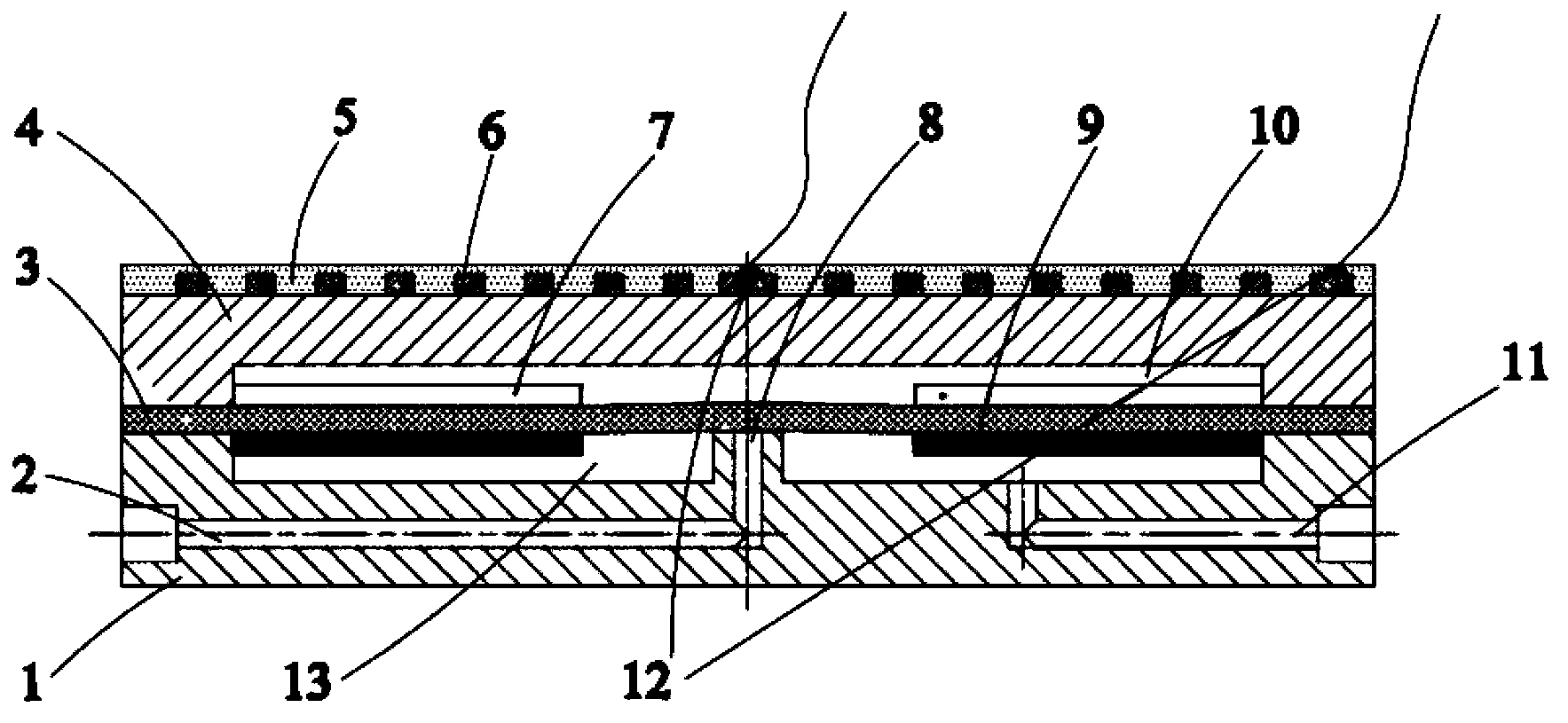
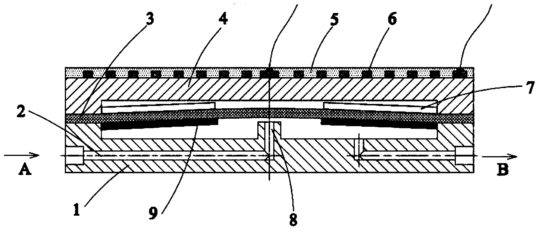
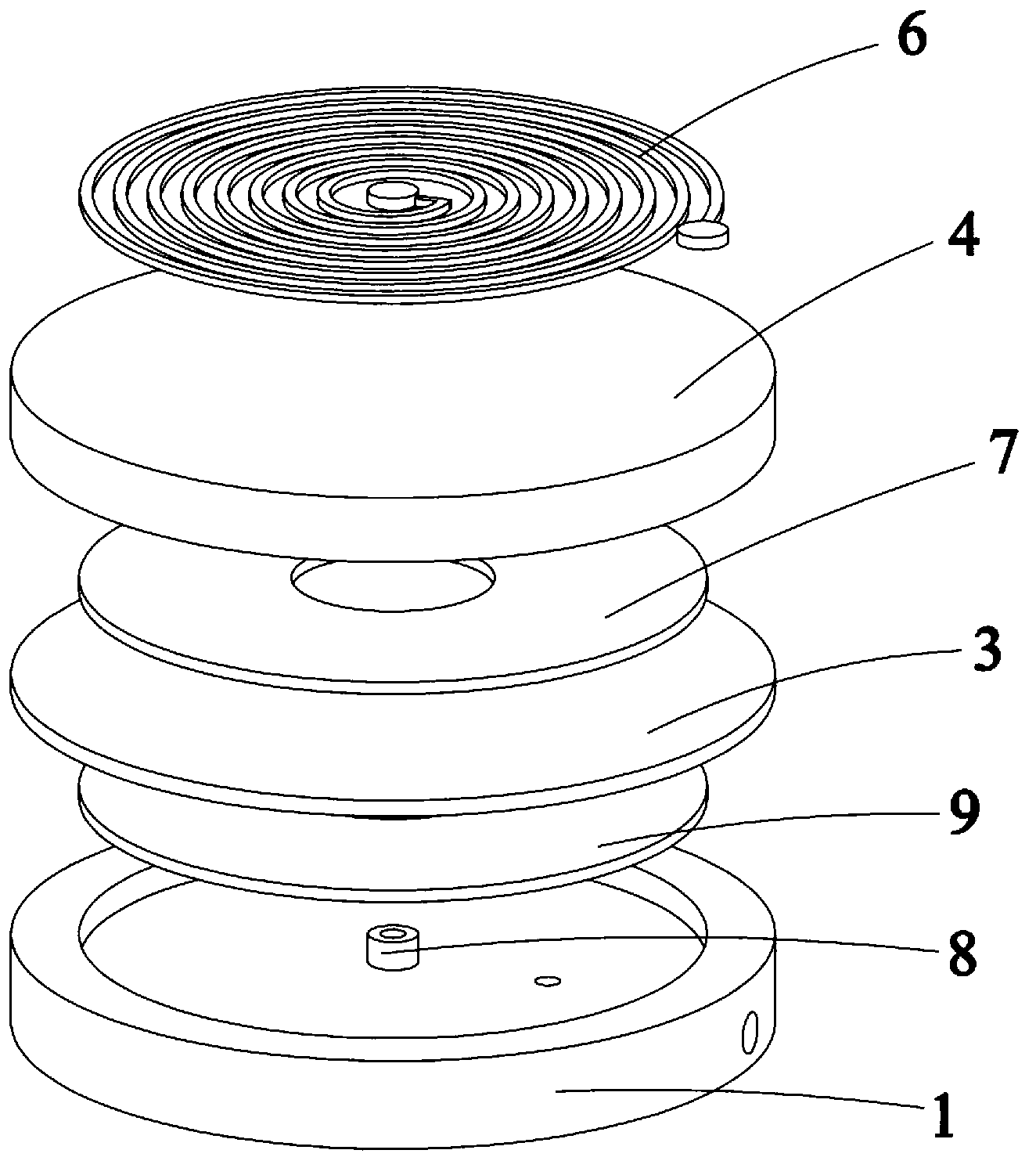
[0023] As shown in the figure, the microvalve includes a lower valve body 1 , a substrate 3 laminated on the lower valve body 1 , an upper valve body 4 and a planar spiral coil 6 in sequence.

[0024] The bottom of the lower valve body is provided with a liquid inlet channel 2 and a liquid outlet channel 11 along the radial direction, a liquid cavity 13 is provided on the upper part of the lower valve body, and a vertical channel 2 is provided at the center of the lower valve body. The upward flow channel opening 8 communicating with the liquid cavity, the flow channel opening 8 protrudes from the bottom surface of the liquid cavity; the liquid outlet channel 11 communicates with the liquid cavity;

[0025] The upper surface of the substrate 3 is coated with a film 7 with a reverse magnetostrictive effect, and the lower surface is coated with a film 9 with a positive magnet...


PUM


Abstract

The invention discloses a planar coil driving-type microvalve based on a super-magnetostriction film driver, which comprises a lower valve body (1), basal pieces (3), an upper valve body (4) and planar spiral coils (6), wherein the basal pieces (3) are sequentially laminated on the lower valve body (1); the bottom part of the lower valve body is respectively provided with a liquid inlet flow channel (2) and a liquid outlet flow channel (11) in the radial direction; a liquid chamber (13) is formed at the upper part of the lower valve body; the liquid inlet flow channel (2) is provided with a vertical upward flow channel mouth communicated with the liquid chamber; the liquid outlet flow channel (11) is communicated with the liquid chamber; inverse magnetostriction-effect films (7) are plated on the upper surfaces of the basal pieces (3); joule magnetostriction-effect films (9) are plated on the lower surfaces of the basal pieces (3); and after the planar spiral coils (6) are electrified, under the action of the excitation magnetic field, the magnetostriction film driver deforms and upward bends to open the working liquid flow channel so as to turn on / off the loop of a hydraulic system. The planar coil driving-type microvalve based on a super-magnetostriction film driver has the characteristics of small size, easiness in miniaturation, high response speed, strong controllability and the like.

Description

technical field [0001] The invention relates to the technical field of micro-fluid valves in precision instruments, in particular to a planar coil-driven micro-valve based on a giant magnetostrictive film driver. Background technique [0002] Microvalve is a device that controls the fluid in the microfluidic system. Its function is to realize the switch of the fluid channel and the control of the flow. It is one of the most important components in the microfluidic system and has been widely used in fluid control Micro-transport and precise flow control and other occasions. Such as micro-biochemical detection, micro-drug delivery, micro-fuel supply, biochips and many other fields. At present, active microvalves that are widely researched and applied mostly adopt piezoelectric drive, electrostatic drive, thermal drive and electromagnetic drive. Both piezoelectric drive and electrostatic drive rely on high voltage operation and are not easy to be controlled by conventional cir...

Claims


Application Information

Patent Timeline
IPC IPC(8): F16K7/14F16K31/06
Inventor 王传礼周禾清邓海顺田东林潘广香
Owner ANHUI UNIV OF SCI & TECH
Learn More