Space optical remote sensor main bearing plate structure adopting embedded part

A technology of space optical remote sensing and main bearing plate, applied in the field of space optical remote sensing, can solve the problems of mutual separation and destruction of embedded parts and carbon fiber materials, small contact area of ​​installation surface, small effective contact area, etc., to increase effective contact Area, enhanced structural rigidity and structural strength, and the effect of ensuring consistency

Active Publication Date: 2012-11-28
CHANGGUANG SATELLITE TECH CO LTD
View PDF4 Cites 11 Cited by
  • Summary
  • Abstract
  • Description
  • Claims
  • Application Information

AI Technical Summary

Problems solved by technology

The disadvantages of this support structure are: the contact area of ​​the installation surface is small, and the installation accuracy is low; the contact surface between the embedded part and the carbon fiber composite material is only processed with a threaded surface to enhance the bonding strength, the effective contact area is small, and the connection strength is weak. The rigidity and strength to prevent the axial movement of the embedded part and the axial rotation around the embedded part are low; under the action of a large external load, the embedded part and the carbon fiber material may be separated and damaged from each other

Method used


Image

  • Space optical remote sensor main bearing plate structure adopting embedded part
  • Space optical remote sensor main bearing plate structure adopting embedded part
  • Space optical remote sensor main bearing plate structure adopting embedded part

Examples


Embodiment Construction

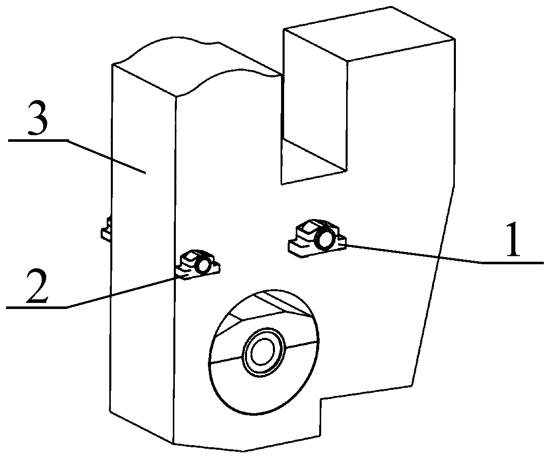
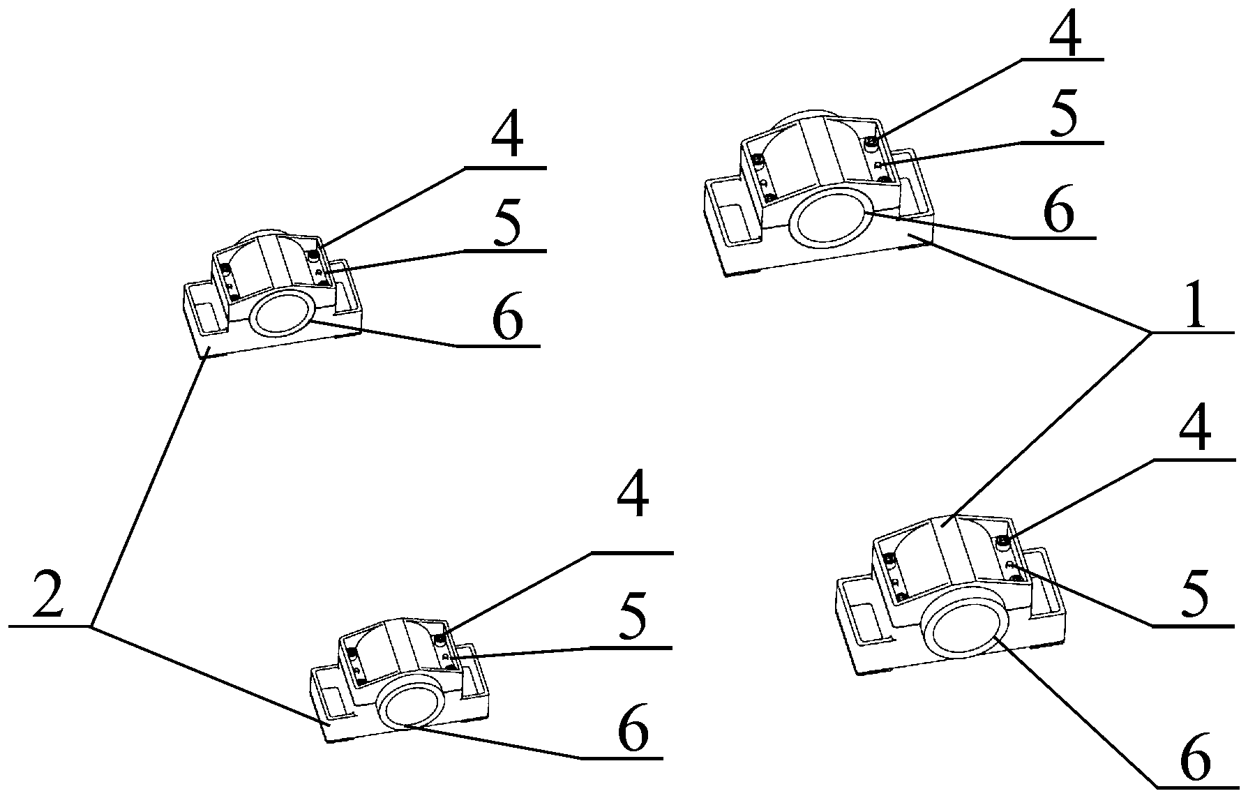
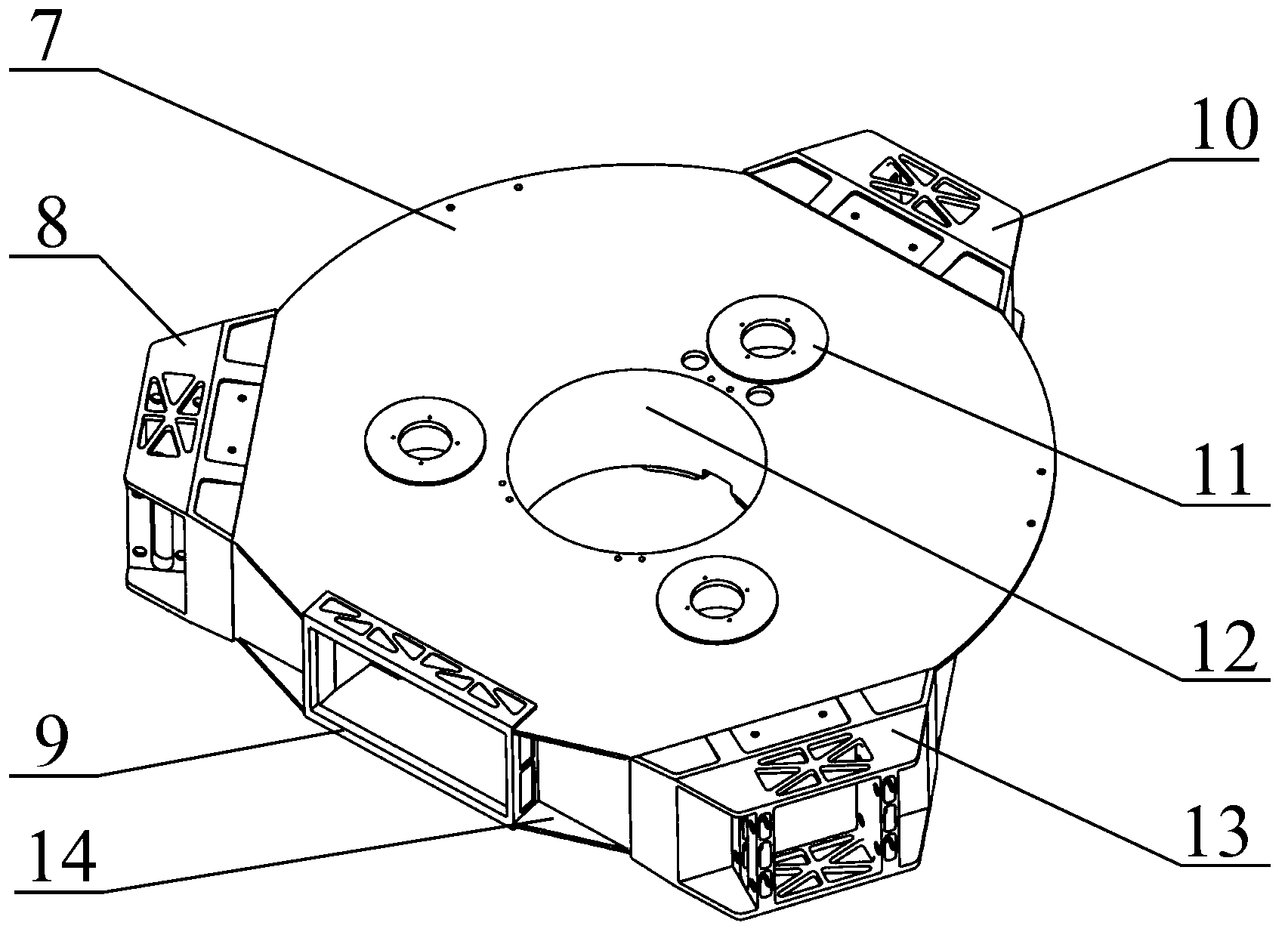
[0015] The invention according to Figure 3 to Figure 7 The implementation of the shown structure, the technical solution of the present invention includes: the main bearing plate 7, the first truss embedded block 8, the third mirror embedded block 9, the second truss embedded block 10, the main mirror embedded block 11, the main bearing plate Central light hole 12, third truss embedded block 13, main bearing plate lower surface 14, folding mirror embedded block 15, bias current embedded block 16, main mirror embedded block inlay hole 17, longitudinal rib groove 18, transverse rib groove 19 , 20 transverse ribs, 21 longitudinal ribs. Among them, the main bearing plate 7 is made of carbon fiber composite material, and all embedded parts are made of titanium alloy material. When manufacturing the main bearing plate 7, the design of mutual inlay and integral molding is adopted, and the transverse ribs 20 and longitudinal ribs 21 of the main mirror embedding block 11 are embedded...


PUM


Abstract

The invention discloses a space optical remote sensor main bearing plate structure adopting an embedded part, and belongs to the technical field of space optical remote sensing, and relates to a main bearing plate structure of the embedded part. The technical problem to be solves is to provide a space optical remote sensor main bearing plate structure adopting an embedded part. The technical scheme is as follows: the structure comprises a main bearing plate front panel, a first truss embedded block, a second truss embedded block, a third truss embedded block, a three-mirror embedded block, a main mirror embedded block, a main bearing plate central hole, a main bearing plate back panel, a folded mirror embedded block, a bias current embedded block, a main mirror embedded block socket, a longitudinal bar groove, a transverse bar groove, a transverse bar and a longitudinal bar. By virtue of the embedded blocks on the main bearing plate, the corresponding mirror assemblies and the other supporting structure assemblies are mounted and located to form a main structure of the space optical remote sensor. The transverse bar and the longitudinal bar are arranged on a contact surface between each embedded block and the bearing plate, so that the effective contact area with a carbon fiber composite material is enhanced; the structure rigidity is reinforced; and the structure reliability is improved.

Description

Technical field: [0001] The invention belongs to the technical field of space optical remote sensing, and in particular relates to a main bearing plate structure using embedded embedded parts in a space optical remote sensor. Background technique: [0002] In the space optical remote sensor, the main bearing plate is the main supporting part of the whole machine structure. All optical mirror components and all supporting structure components are installed and positioned based on the main bearing plate, and are integrated together. Form a complete imaging optical system structure. Due to the large mass of the mirror components in the optical system, the requirements for the spatial relative position accuracy of each other are very high, resulting in high requirements for the rigidity and shape position accuracy of the support structure of the mirror components. In the space optical remote sensor, the main reflector is installed on the front panel of the main bearing plate, t...

Claims


Application Information

Patent Timeline
Patent Type & Authority Applications(China)
IPC IPC(8): G02B7/182
Inventor 安源金光贾学志李宗轩
Owner CHANGGUANG SATELLITE TECH CO LTD
Why Eureka
Try Eureka