Self-humidifying fuel cell

A fuel cell and self-humidification technology, applied in fuel cells, fuel cell additives, circuits, etc., can solve problems such as differences in the performance of single cells, improve power density and energy density, improve stability, and reduce power consumption Effect

Inactive Publication Date: 2012-11-28
JIANGSU ICE CITY INSULATION MATERIALS STOCK
View PDF8 Cites 13 Cited by
  • Summary
  • Abstract
  • Description
  • Claims
  • Application Information

AI Technical Summary

Problems solved by technology

Due to the uneven gas distribution, it is easy to cause the difference in the performan

Method used


Image

  • Self-humidifying fuel cell
  • Self-humidifying fuel cell
  • Self-humidifying fuel cell

Examples


Embodiment 1

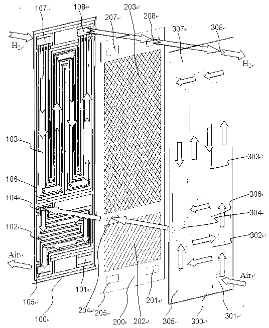
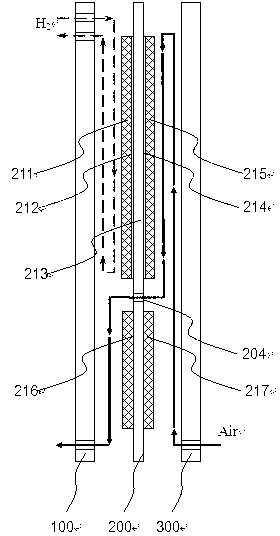
[0027] figure 1 with figure 2 An embodiment of a self-humidifying fuel cell of the present invention is shown in, figure 1 It is a schematic diagram of the three-dimensional decomposition structure of the fuel cell of the invention, figure 2 A schematic diagram of the side. from figure 1 It can be seen from the figure that the self-humidifying fuel cell is formed by stacking two fuel cell cells, and each fuel cell cell contains an anode flow field plate 100, a membrane electrode 200 and a cathode flow field plate 300 in sequence, and the lower part of the fuel cell cell It is the humidification part of the fuel cell, and the upper part is the reaction part of the fuel cell. The upper part of the membrane electrode 200 is provided with a hydrogen gas inlet hole 207 and a hydrogen gas exhaust hole 208 , and the lower part is provided with an air inlet hole 201 and an air exhaust hole 205 .

[0028] In the humidification zone 202 and the reaction zone 203 of the single mem...

Embodiment 2

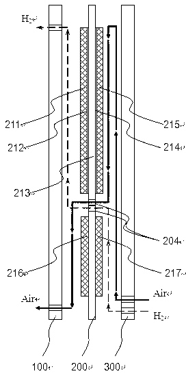
[0035] image 3 Shown is another embodiment, utilizing the air tail gas to simultaneously humidify the hydrogen and air intake. In this embodiment, the air flow mode is the same as that in the first embodiment, except that when hydrogen gas enters the single fuel cell, it first flows through the cathode humidification flow field 302 on the cathode flow field plate. At this time, the humidified flow field on the cathode flow field plate 300 is divided into two parts, one part is the air humidified flow field, and the other part is the hydrogen humidified flow field, and the air humidified flow field and the hydrogen humidified flow field pass through the cathode The seals 306 are separated from each other to prevent hydrogen and air from mixing with each other. The corresponding membrane electrode humidification area is also divided into two parts: hydrogen humidification area and air humidification area. After hydrogen enters the hydrogen humidification zone on the cathode f...


PUM


Abstract

The invention discloses a self-humidifying fuel cell. The fuel cell is formed by superposing a plurality of monomers, wherein each monomer comprises a cathode flow field plate, an anode flow field plate, a sealing piece and a film electrode; the film electrode consists of a reaction area and a humidifying area; corresponding reaction areas and humidifying areas are contained in the anode flow field plate and the cathode flow field plate; the cathode reaction air enters the fuel cell monomers, passes through the humidifying area of the cathode flow field plate and enters the reaction area to participate an electrochemical reaction; the completely reacted air enters the humidifying area on the anode flow field plate through a gas channel formed on the film electrode; and the air passing through the reaction area has high humidity, and the water can humidify the inlet cathode reaction air through the proton exchange film of the humidifying area on the film electrode. The inlet air is humidified by directly utilizing the air exhaust, the humidifying area and the reaction area are positioned on the same film electrode, the fuel cell is simple in structure, the fuel cell stack integration is not influenced, the water management problem of the fuel cell can be greatly solved, and the power density of a fuel cell system is improved. The fuel cell can be applied to various fields of various electronic equipment power supplies, the uninterrupted power system, the electric automobile engine system and the like.

Description

technical field [0001] The invention belongs to the field of fuel cells, in particular to the proton exchange membrane fuel cell technology using no external humidification. Background technique [0002] A fuel cell is a continuous power generation device that converts chemical energy in externally supplied fuel and oxidant into electrical energy. The current fuel cell technology is mainly divided into several types according to different electrolytes, such as alkaline fuel cells, phosphoric acid fuel cells, molten carbonate fuel cells, proton exchange membrane fuel cells and solid oxide fuel cells. Proton Exchange Membrane Fuel Cell (PEMFC) is the most mature and most widely used fuel cell. [0003] In proton exchange membrane fuel cells, the electrolyte is a proton exchange membrane with proton transfer performance, and perfluorosulfonic acid membrane is widely used at present. The transfer of protons in the electrolyte membrane depends on water molecules as the conduct...

Claims


Application Information

Patent Timeline
IPC IPC(8): H01M8/04H01M8/04119
CPCY02E60/50
Inventor 朱浩朱艾成刘发喜董文超王益军
Owner JIANGSU ICE CITY INSULATION MATERIALS STOCK
Why Eureka
Try Eureka