Drill with coolant holes

A technology for cooling holes and drill bits, which is applied in drilling/drilling equipment, drill repairing, twist drills, etc. It can solve problems such as accelerated wear, insufficient cooling fluid distribution, and decreased hole processing accuracy to achieve effective lubrication and cooling. , promote the increase, and promote the effect of supply

Inactive Publication Date: 2012-11-28
MITSUBISHI MATERIALS CORP
View PDF13 Cites 7 Cited by
  • Summary
  • Abstract
  • Description
  • Claims
  • Application Information

AI Technical Summary

Problems solved by technology

Therefore, in either case, the coolant may not be sufficiently distributed between the sub-flank surface and the inner peripheral surface of the machined hole
The margin portion located ...

Method used


Image

  • Drill with coolant holes
  • Drill with coolant holes
  • Drill with coolant holes

Examples


Embodiment 1

[0156] Hereinafter, with respect to the ratios of the intervals A1, B1, C1, E1, the width F1, and the angle α1 to the angle β1 in the above-mentioned embodiment, examples are given to verify that the above-mentioned ranges are appropriate.

[0157] Here, the ratios of the intervals A1, B1, C1, E1, the width F1, and the angle α1 to the angle β1 are set as examples (standard: BM) within the range of the above-described embodiment. On the other hand, those exceeding the upper limit value and the lower limit value of the range in the above-described embodiment are set as comparative examples. Furthermore, CAE analysis of Examples and Comparative Examples was performed. From the obtained result, the rigidity with respect to the torque when an Example was made into 100% was analyzed by relative evaluation. In addition, a fluid analysis of the flow of coolant flowing in the cooling holes is performed.

[0158] Here, the analysis of stiffness with respect to torque is performed unde...

Embodiment 11

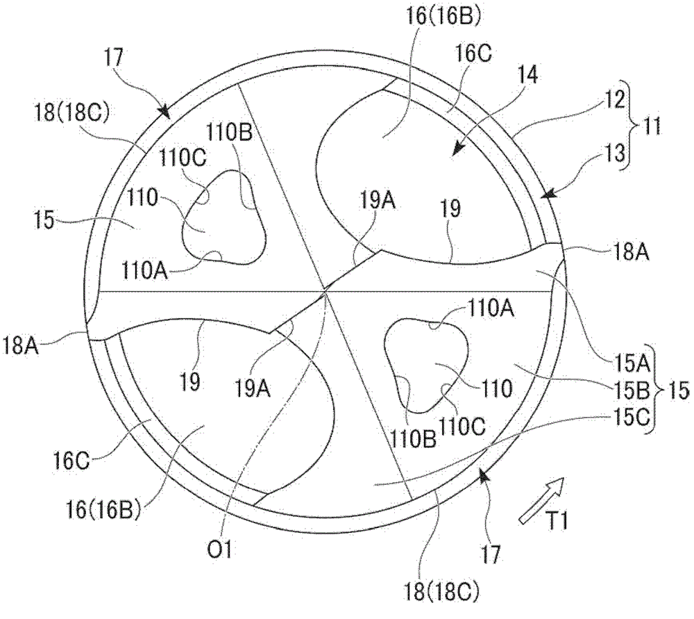
[0165] The example (BM) in which the interval C1 of the outer peripheral hole wall surface 110C of the cooling hole 110 and the outer peripheral wall surface (outer peripheral flank surface 18C) was set to 13% of the outer diameter D1 of the cutting edge 19 as described above was set to 100%. In this case, in the first comparative example, the interval C1 was set to 23% exceeding 20% ​​of the outer diameter D1 of the cutting edge 19 . In the second comparative example, the interval C1 was set to 3% lower than 5% of the outer diameter D1 of the cutting edge 19 . exist Figure 13 The results of relative stiffness with respect to torque based on CAE analysis of Examples and Comparative Examples are shown in FIG. Furthermore, in Figure 14 The results of the relative comparison of the outlet flow rates of the cooling holes of the Example and the Comparative Example are shown in FIG.

[0166] According to this result, in the first comparative example in which the distance C1 bet...

Embodiment 12

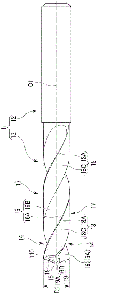
[0168] The interval A1 is the interval between the front hole wall surface 110A of the cooling hole 110 and the front groove wall surface 16A of the chip discharge groove 14 . The interval B 1 is the interval between the rear hole wall surface 110B of the cooling hole 110 and the rear groove wall surface 16B of the chip discharge groove 14 . The example (BM) in which both the interval A1 and the interval B1 are 10% of the outer diameter D1 of the cutting edge 19 is assumed to be 100%. In this case, in the first comparative example, the interval A1 and the interval B1 were set to 17% exceeding 15% of the outer diameter D1 of the cutting edge 19 .

[0169] In the second comparative example, the interval A1 and the interval B1 were set to 2%, which is lower than 3%. exist Figure 15 Results of relative stiffness to torque based on CAE analysis for these Examples and Comparative Examples are shown in . Furthermore, in Figure 16 The results of the relative comparison of the ou...


PUM


Abstract

A drill provided with coolant holes, comprising: a drill body rotating about the axis thereof; cutting edge sections having top clearance surfaces; cutting debris discharge grooves each having a front groove-wall surface facing forward in the rotational direction of the drill body and also each having a rear groove-wall surface facing rearward in the rotational direction; cutting edges each formed at the ridge at which a front groove-wall surface and a top clearance surface intersect each other; land sections each formed between the cutting debris discharge grooves adjacent to each other in the rotational direction; and coolant holes formed by boring in the land sections and open in the top clearance surfaces. The coolant holes each include: a front hole-wall surface located ahead in the rotational direction and having a constant distance to the front groove-wall surface of a cutting debris discharge groove; a rear hole-wall surface located behind the rotational direction and having a constant distance to the rear groove-wall surface of a cutting debris discharge groove; and an outer peripheral hole-wall surface located on the outer peripheral side of the drill body and having a constant distance to the outer peripheral wall surface of a land section.

Description

technical field [0001] The present invention relates to a drill with a cooling hole in which a cooling hole for supplying a cooling fluid such as a cutting oil is formed in a cutting edge portion of a front end portion of a drill main body for drilling. [0002] This application is based on Japanese Patent Application Nos. 2009-142441, 2010-095374, 2010-095375, and 2010-095376 filed in Japan on April 16, 2010, filed in Japan on June 15, 2009 Priority is claimed and its contents are hereby cited. Background technique [0003] In drills with cooling holes, the cooling holes are generally mostly circular in cross-section. In order to achieve an increase in the supply amount of the cooling liquid and efficient supply, for example, Patent Document 1 proposes that the axial cross-sectional shape of the cooling hole is such that the distance between the inner wall surfaces gradually decreases from the approximate center of the cooling hole toward the center of rotation. droplet s...

Claims


Application Information

Patent Timeline
IPC IPC(8): B23B51/06B23B51/00
CPCB23B2222/80B23B2251/406B23B51/06B23B2251/44Y10T408/455B23B51/02B23B51/0486
Inventor 松田信行东裕之成毛康一郎山本匡柳田一也
Owner MITSUBISHI MATERIALS CORP
Why Eureka
Try Eureka