Driving system for railroad vehicle

一种驱动系统、铁路车辆的技术,应用在铁路车辆、电力制动系统、车辆储能等方向,能够解决重新进行供油设施等问题,达到机动性高的效果

Active Publication Date: 2012-11-28
HITACHI LTD
View PDF6 Cites 15 Cited by
  • Summary
  • Abstract
  • Description
  • Claims
  • Application Information

AI Technical Summary

Problems solved by technology

[0015] That is, there is a problem that in order to realize the direct connection between the non-electrified section and the electrified section of the hybrid vehicle, it is necessary to re-invest in equipment such as fuel supply facilities even in the electrified section.

Method used


Image

  • Driving system for railroad vehicle
  • Driving system for railroad vehicle
  • Driving system for railroad vehicle

Examples


Embodiment

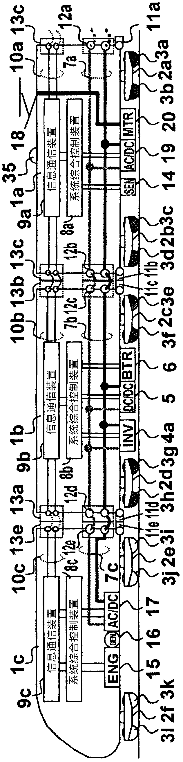
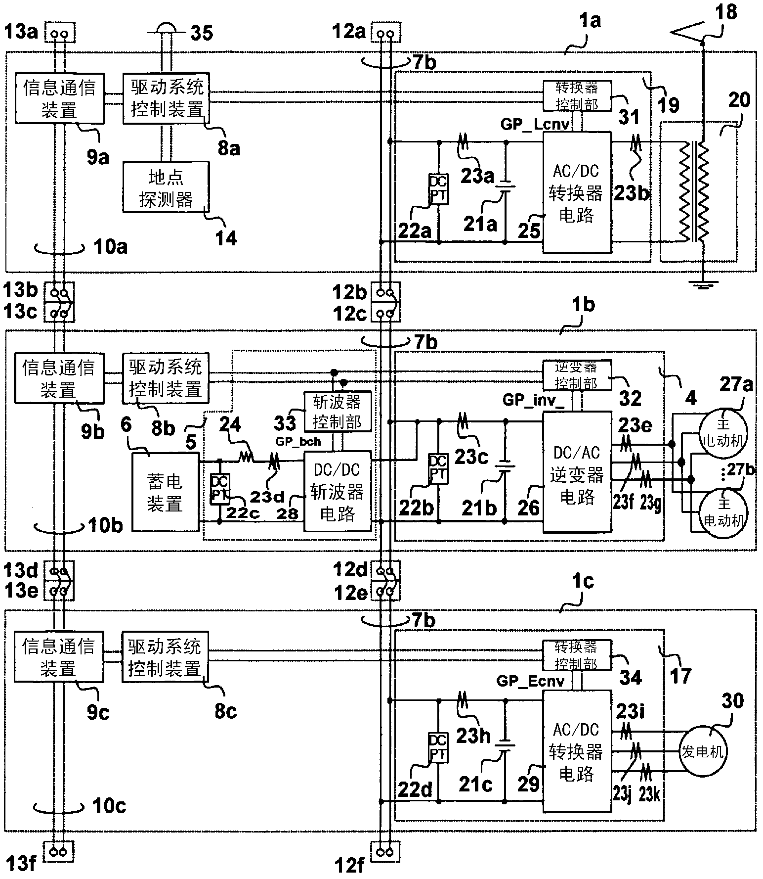
[0031] figure 1 It is a figure which shows the device structure of one Embodiment in the drive system of the railway vehicle of this invention.

[0032] Vehicles 1a, 1b, and 1c are partial vehicles constituting a train formation. The third vehicle 1a is equipped with workshop connectors 11a, 11b, the second vehicle 1b is equipped with workshop connectors 11c, 11d, the first vehicle 1c is equipped with workshop connectors 11e, 11f, and vehicle 1a and vehicle 1b are connected to the workshop through the workshop connector 11b. Connector 11c, vehicle 1b and vehicle 1c are connected through workshop connector 11d and workshop connector 11e.

[0033]The vehicle 1a is supported on an unillustrated track surface via a bogie 2a via axles 3a, 3b, and via a bogie 2b via axles 3c, 3d. The vehicle 1b is supported on an unillustrated predetermined surface by passing through axles 3e, 3f via a steering cart 2c, and via axles 3g, 3h via a steering cart 2d. The vehicle 1c is supported on ...


PUM


Abstract

Provided is a high mobility railroad vehicle system configured to reciprocally carry out a direct drive between a non-electrically driven section and an electrically driven section without installing new facilities such as oil supply equipment and without considering distinction between the non-electrically and electrically driven sections. A railroad vehicle system is provided with an overall control apparatus to respectively control an external electric power supply means, an internal electric power supply means, an electricity storage means, electric power conversion means and a motor driving means. The railroad vehicle system judges or previously notifies as to whether the present driving railroad section is the electrically driven section or non- electrically driven section in accordance with driving position information received from a position information generation means such as a ground facility on a railroad equipped outside of the vehicle and a global positioning system (GPS). The system cuts off from an external electric power source in the non-electrically driven section and carries out a smooth shifting control in order to connect to the external electric power source in the electrically driven section.

Description

technical field [0001] The present invention relates to a drive system for a railway system, and in particular to a technology that includes an external power supply unit, a power generation unit, and a power storage unit, and uses the power obtained from these units to drive a railway vehicle. Background technique [0002] A railway vehicle is characterized in that it travels with iron wheels rolling on the track surface, and therefore has less running resistance than an automobile. In particular, in recent electrified railway vehicles, when braking, the main motor acts as a generator to obtain braking force, and at the same time, regenerative braking control is performed to return the electric energy generated by the main motor to the overhead line to be used as a power source for other vehicles. and re-use the energy of action. An electrified railway vehicle equipped with such regenerative braking can run with about half the energy consumption compared to an electrified ...

Claims


Application Information

Patent Timeline
Patent Type & Authority Applications(China)
IPC IPC(8): B60L13/00B60L11/12B61C3/02B61C9/24B60L50/10B60L50/15
CPCB60L2260/26Y02T10/7077B60L11/1801B60L9/28Y02T30/16B60L11/02Y02T10/7005B61C7/04B60L9/00B61C3/02Y02T30/12B60L7/16B60L2200/26Y02T10/70B60L50/53B60L50/10Y02T30/00Y02T10/7072B60L13/00B61C9/24
Inventor 岛田基巳金子贵志望月健人石田诚司
Owner HITACHI LTD
Why Eureka
Try Eureka